
Grip

A grip and resin technology, applied in the field of grips, can solve the problems of loss of appearance, grip, grip, surface is difficult to be heated, power consumption increases, etc., to achieve improved appearance, easy insertion, good installation and durability sexual effect

Inactive Publication Date: 2011-05-18
HONDA MOTOR CO LTD
View PDF0 Cites 1 Cited by
  • Summary
  • Abstract
  • Description
  • Claims
  • Application Information

AI Technical Summary

Problems solved by technology

However, in this method, the thicker the resin layer, the more difficult it is to heat the surface, and the power consumption will increase accordingly, and sometimes it cannot be heated to a temperature that can warm hands
[0006] Conversely, if the resin layer is made thinner, it will be easy to heat, but it will damage the appearance and the grip when holding the grip

Method used


Image

  • Grip
  • Grip
  • Grip

Examples


Embodiment Construction

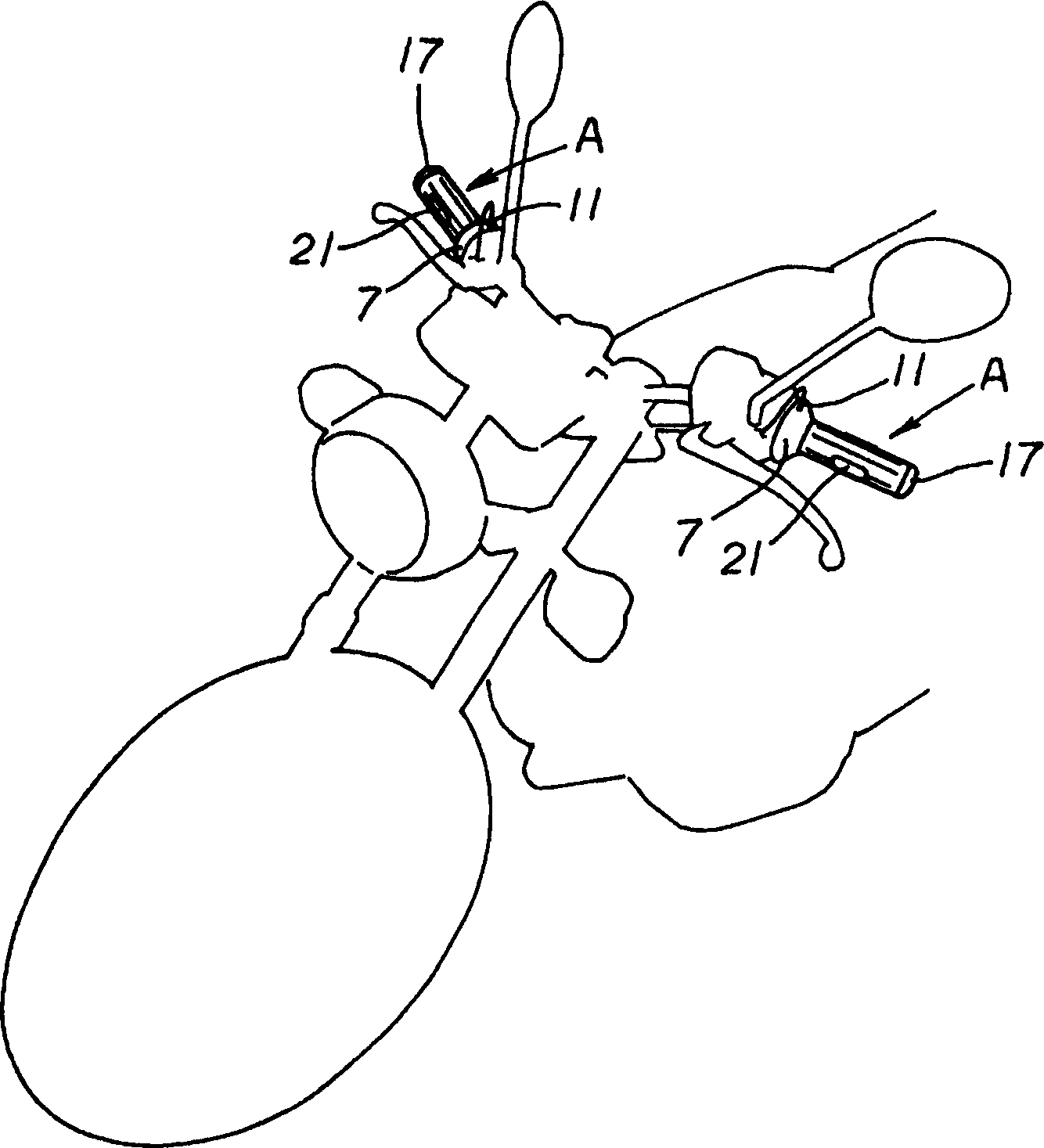
[0047] Hereinafter, preferred embodiments of the present invention (how to carry out the invention) will be described. First show and explain the effect of the present invention according to accompanying drawing.

[0048] Firstly, the technical solutions 1 to 6 of the present invention characterized by the installation structure of the plates 21 are described.

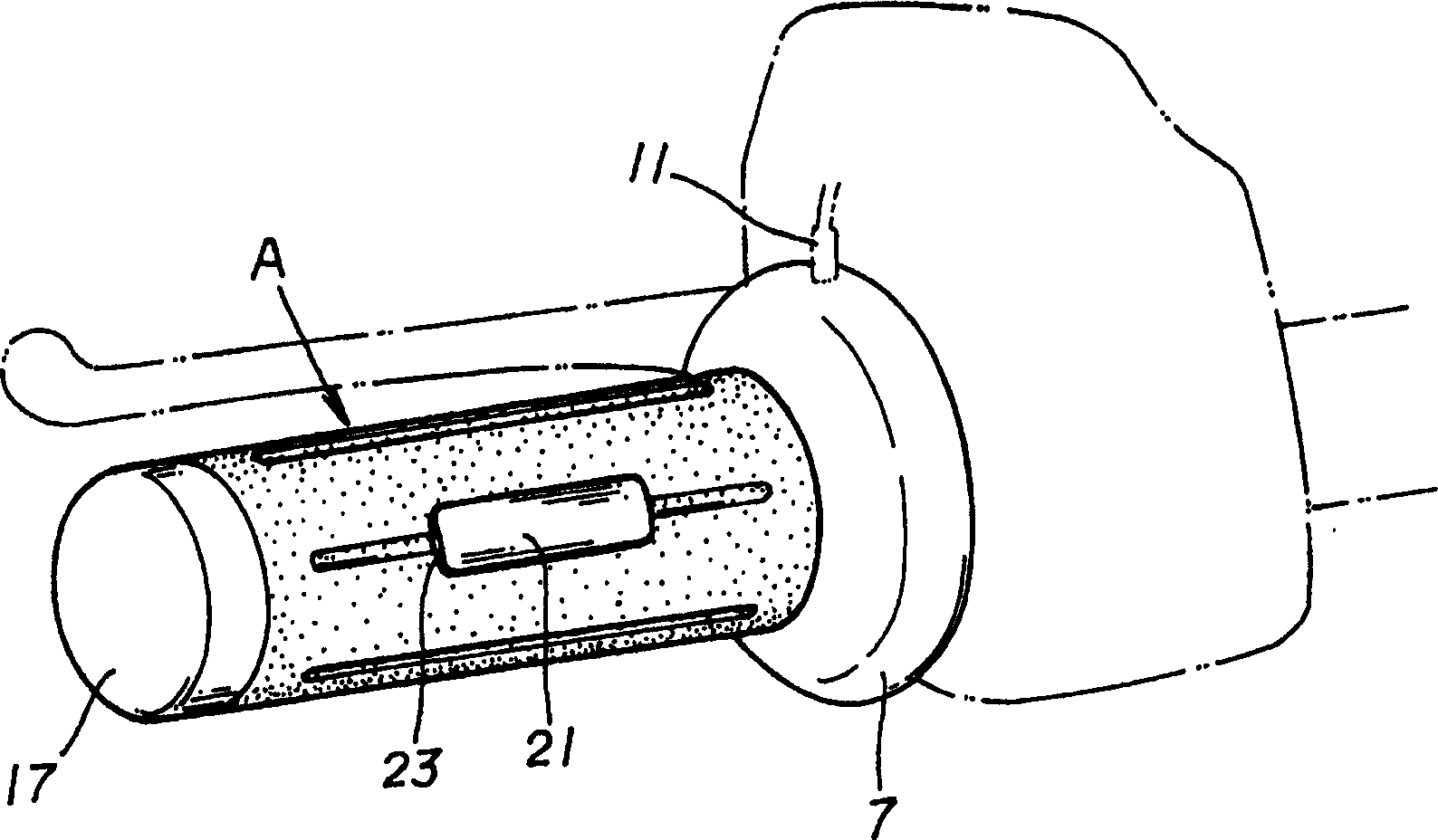
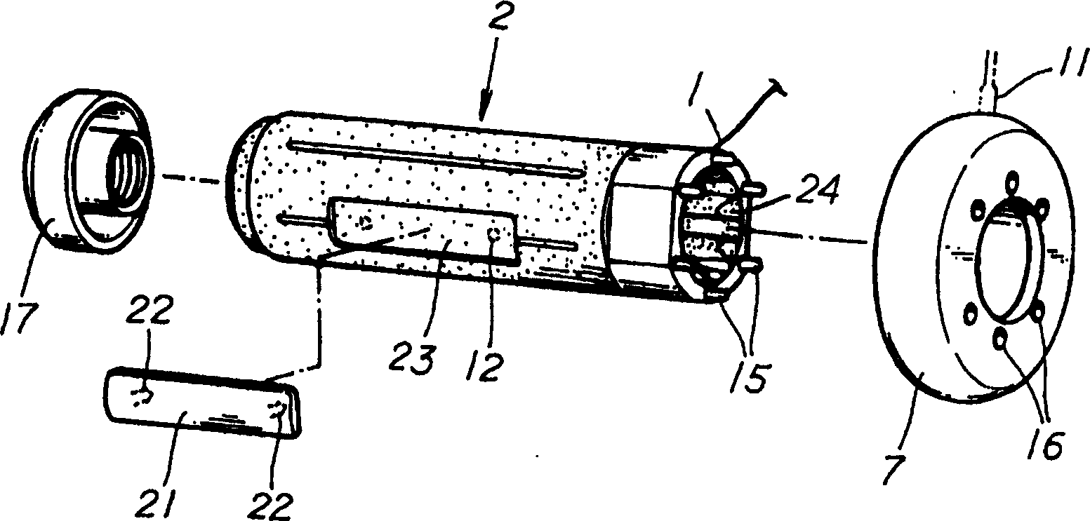
[0049] A resin layer is formed on the surface and the inside of the inner member 2, and the inner member 2 is provided with a resin flow hole 12 connecting the resin on the surface and the inside, and the resin flow hole 12 is used as a mounting hole. An insertion rod 22 is attached to the plate 21 , and the insertion rod 22 on the plate 21 is inserted into the resin flow hole 12 to lock and fix the plate 21 to the surface of the handle body A.

[0050] For example, when the vehicle is a motorcycle, the handlebar tube or accelerator controller tube becomes the mounting part 4 of the grip, and the internal member 2 is ...


PUM


Abstract

The invention discloses an assembling hole, which is characterized by the following: carding resin flowing hole in the plug-in rod on the board; fixing board on the handle surface; forming effective heat conductive resin surface; allocating resin packing mould to form handle bulk; or casing outer cylinder part in the covered resin directly or through resin component; setting resin flowing hole onthe non-heater position of plug-in rod; fixing board on the surface part of handle bulk.

Description

technical field [0001] The present invention relates to, for example, handles provided on handlebars of motorcycles, four-wheeled or three-wheeled cars, snowmobiles, jet skis, etc., or handles directly used as these handlebars. Background technique [0002] For example, when the plates showing characters, patterns, etc. such as trademarks and advertisements are additionally arranged on the surface of the handle, a recess for installing the plates is formed on the surface of the handle, and the plates are fitted into the recesses, or by means of Adhesive (such as adhesive tape) is used for bonding and fixing, but due to the action of grip force, throttle control operation, etc., loads are frequently applied to the plate in the direction of rotation, so when using this mounting structure for a long time Under the circumstances, the installation strength of the plate will be insufficient. [0003] In addition, fastening by screws also has a problem of poor workability, especia...

Claims


Application Information

Patent Timeline
Patent Type & Authority Patents(China)
IPC IPC(8): B62K21/26B62J33/00
Inventor 大石康夫东裕美子
Owner HONDA MOTOR CO LTD
Learn More