Disc drive apparatus

A disk drive, optical disk drive technology, applied in the configuration/installation of heads, digital recording/reproduction, instruments, etc., can solve problems such as dependence, affecting controller capabilities, mechanical vibration, etc.

Inactive Publication Date: 2006-11-08
KONINKLIJKE PHILIPS ELECTRONICS NV
View PDF2 Cites 0 Cited by
  • Summary
  • Abstract
  • Description
  • Claims
  • Application Information

AI Technical Summary

Problems solved by technology

One disadvantage of this method is that it relies on the data written on the disc; it cannot be applied to blank discs
Another disadvantage is that this method requires complex circuits, in particular circuits for detecting the upper and lower peaks, circuits for filtering to detect the upper and lower envelopes, circuits for analyzing these envelopes and circuit for storing signals in memory
changing control characteristics to better handle one type of disturbance, which can seriously affect the controller's ability to handle another type of disturbance
[0018] Furthermore, the inventors have discovered that a single detection signal is not always a reliable source of information for distinguishing between mechanical shocks and disc defects
In other words, a certain signal can be generated in case of mechanical shock as well as in case of disc defect, so the event can be wrongly identified as disc defect or mechanical shock

Method used


Image

  • Disc drive apparatus
  • Disc drive apparatus
  • Disc drive apparatus

Examples


Embodiment Construction

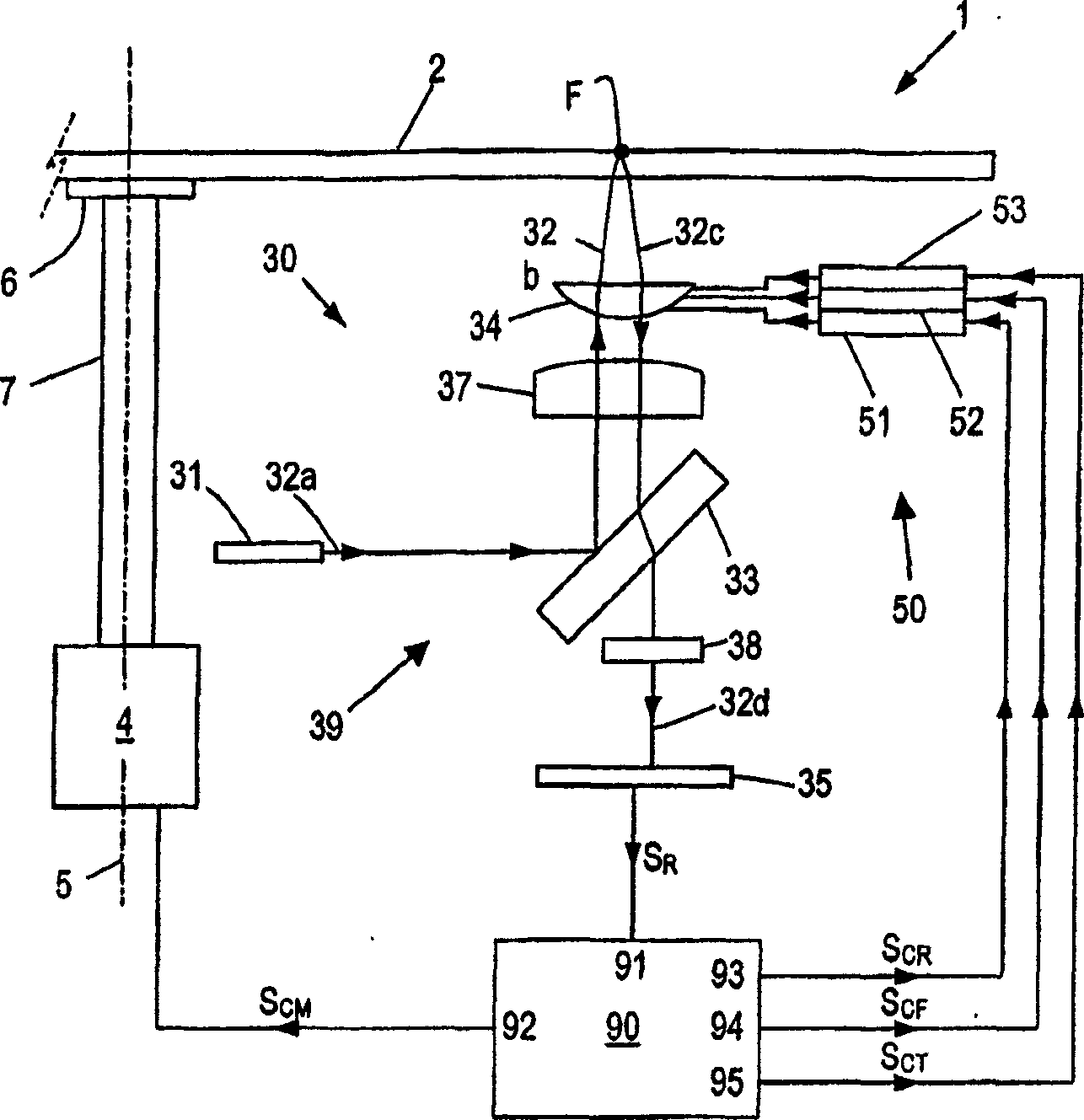
[0032] Figure 1A An optical disc drive device 1 is schematically shown, adapted to store information on, or to read information from, an optical disc 2, usually a DVD or CD. In order to rotate the disk 2 , the disk drive device 1 comprises a motor 4 fixed to a frame (not shown for simplicity), said frame defining an axis of rotation 5 .

[0033] The disk drive apparatus 1 also includes an optical (optic) system 30 for scanning the track of the disk 2 with a light beam (not shown). More specifically, in Figure 1A In the exemplary arrangement shown, the optical system 30 comprises beam generating means 31 , typically a laser, such as a laser diode, arranged to generate a beam 32 . In the following, the different parts of the light beam 32 along the optical (path) path 39 will be indicated with the letters a, b, c etc. appended to the reference number 32 .

[0034] The light beam 32 passes through a beam splitter 33 , a collimator lens 37 and an objective lens 34 to reach (bea...


PUM


Abstract

A method is described for controlling an optical disc drive apparatus (1) of a type comprising: scanning means (30) for scanning a record track of an optical disc (2) and for generating a read signal (SR); actuator means (50) for controlling the positioning of at least one read/write element (34) of said scanning means (30) with respect to the disc (2); a control circuit (90) for receiving said read signal (SR) and generating at least one actuator control signal (SCR) on the basis of at least one signal component of said read signal (SR), the control circuit (90) having at least one variable control parameter. The method comprises the steps of: deriving from said read signal (SR) at least two signals (REn; MIRn) of mutually different type; and varying the setting of said at least one variable control parameter as a function of said at least two signals. An other method is described for discriminating two kinds of disturbances originated by a) disc defects, b) schocks.

Description

technical field [0001] The present invention generally relates to an optical disc drive device for writing / reading information from / to an optical storage disc. Background technique [0002] As is known, an optical storage disc comprises at least one track of storage space in the form of a continuous spiral or a plurality of concentric circles, in which information can be stored in the form of data patterns. Optical discs may be of the read-only type, in which information is recorded during manufacture, which can only be read by a user. Optical storage discs can also be of the writable type, in which information can be stored by the user. In order to write information into the storage space of an optical storage disc, or to read information from the disc, the optical disc drive includes, on the one hand, a rotating device for receiving and rotating the optical disc; A beam of laser beam, and the stored track is scanned with the laser beam. Since the manner in which informa...

Claims


Application Information

Patent Timeline
Patent Type & Authority Applications(China)
IPC IPC(8): G11B7/09
CPCG11B7/0941G11B7/0946G11B7/0948G11B7/09G11B20/18
Inventor M·F·赫特杰斯F·L·M·克利默斯F·B·斯帕林G·A·L·利恩克奈特H·朗夫
Owner KONINKLIJKE PHILIPS ELECTRONICS NV
Why Eureka
Try Eureka