Glue smearing device for coating machine
The technology of a scraping device and a coating machine is applied to the device for coating liquid on the surface, coating and other directions, which can solve the problem of unsatisfactory glue saving effect, and achieve the effect of good transparency and uniform coating stripes.
- Summary
- Abstract
- Description
- Claims
- Application Information
AI Technical Summary
Problems solved by technology
Method used
Image

Examples
Embodiment Construction
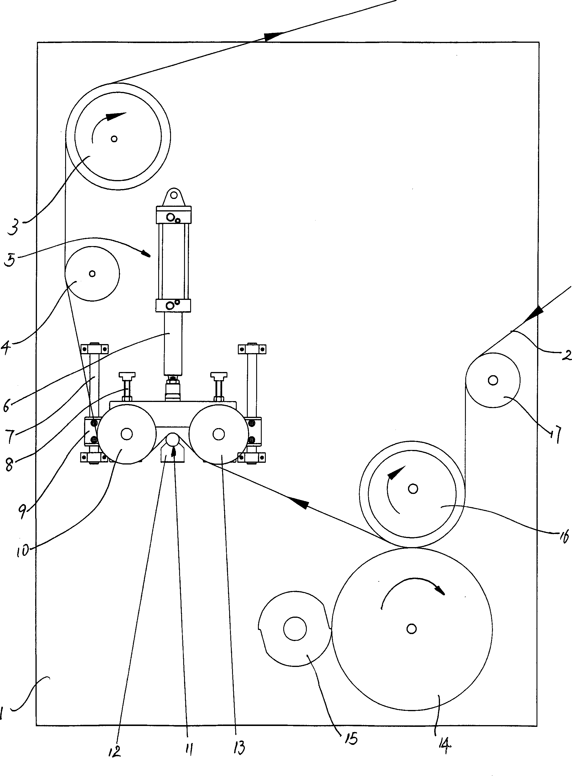
[0014] See attached figure 1 Shown, a kind of squeegee device of coater, this squeegee device is arranged on the gluing head equipment of coater, and is positioned between upper rubber wheel 14 and oven, passes quantitative roller 15 on upper rubber wheel 14 The control of glue amount, base material 2 can be coated evenly after gluing, and the gluing surface of glue layer is thinner; A pressurizing mechanism, the bracket 1 is also provided with a squeegee stick 11, and the squeegee stick 11 and the pressurizing mechanism are used for the substrate 2 after gluing from the squeegee stick 11 It passes between the pressurizing mechanism, and the glued surface of the substrate 2 is pressed on the outer surface of the squeegee rod 11 .
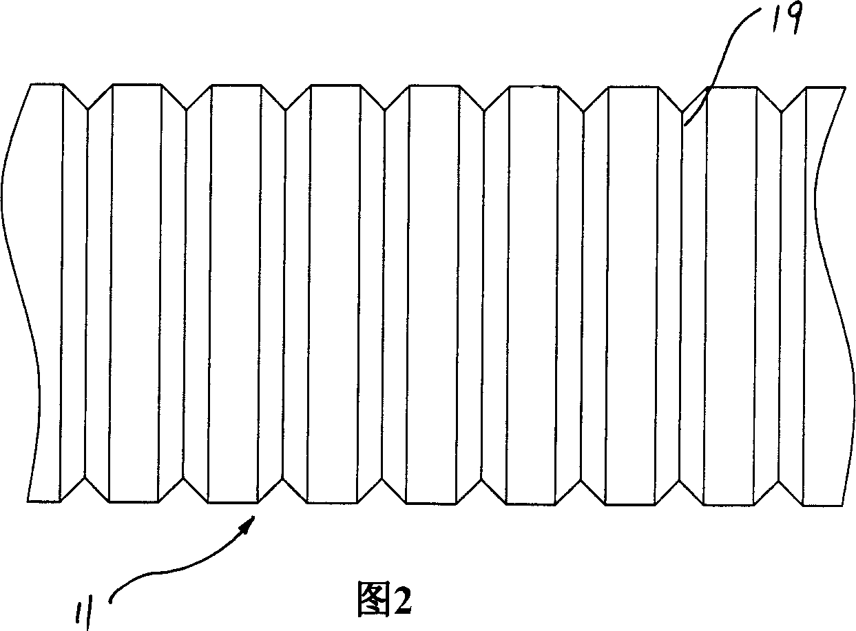
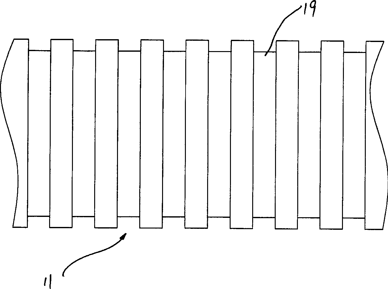
[0015] The circumferential surface of the squeegee stick 11 has a plurality of grooves 19 arranged along the axial direction of the squeegee stick 11, and each of the grooves 19 surrounds a closed circle around the axis of the squeegee stick 11, re...
PUM
 Abstract
Description
Claims
Application Information
 - R&D
- Intellectual Property
- Life Sciences
- Materials
- Tech Scout
- Unparalleled Data Quality
- Higher Quality Content
- 60% Fewer Hallucinations
Browse by: Latest US Patents, China's latest patents, Technical Efficacy Thesaurus, Application Domain, Technology Topic, Popular Technical Reports.
© 2025 PatSnap. All rights reserved.Legal|Privacy policy|Modern Slavery Act Transparency Statement|Sitemap|About US| Contact US: help@patsnap.com