
Image sensing module

An image sensing and magnet technology, applied in optical components, optics, instruments, etc., can solve the problems of increased camera volume, heavy weight and bulky CCD components, etc., and achieve the effect of improving sensitivity and speed

Inactive Publication Date: 2006-11-15
ASIA OPTICAL CO INC
View PDF2 Cites 0 Cited by
  • Summary
  • Abstract
  • Description
  • Claims
  • Application Information

AI Technical Summary

Problems solved by technology

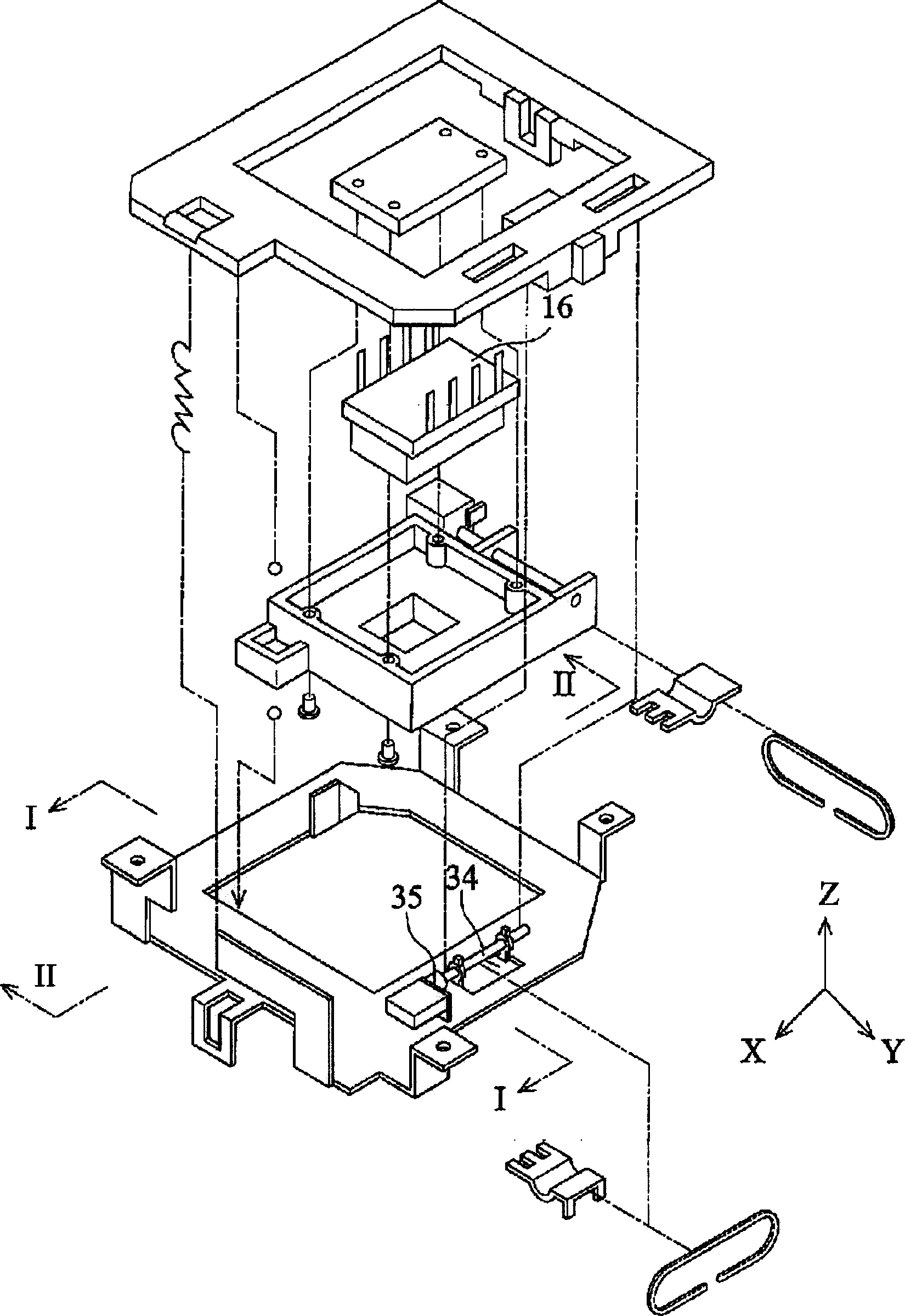
[0005] The piezoelectric component must be constantly driven by voltage in order to properly move the CCD to correct the image; however, the weight of the CCD component is heavier than that of a single lens, making it necessary to use a rather large piezoelectric component to drive the component
Although this method does not reduce the optical imaging quality of the lens, the bulky piezoelectric component increases the size of the camera with this function of correcting or suppressing hand vibration.

Method used


Image

  • Image sensing module
  • Image sensing module
  • Image sensing module

Examples


Embodiment Construction

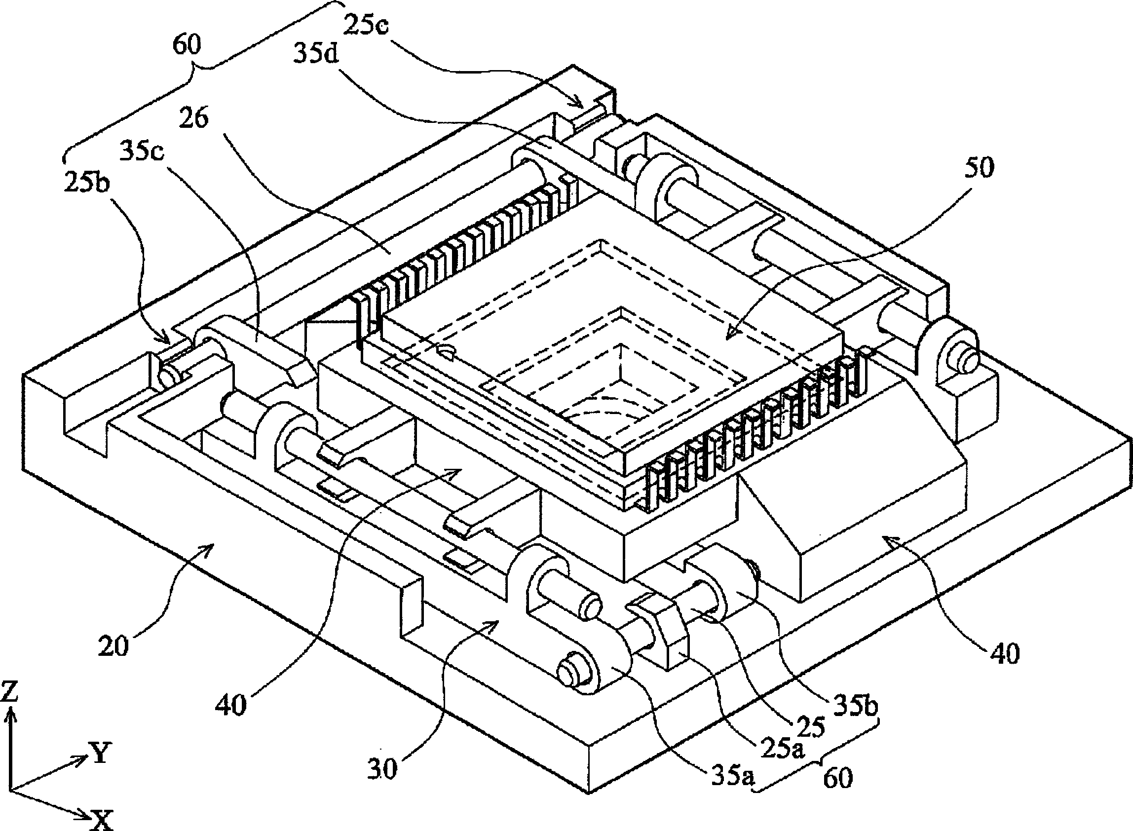
[0029] Before the present invention is described in detail, it should be noted that the relative position terms used in the following descriptions, such as "first direction X", "second direction Y", and "third direction Z" are based on the The marked coordinate direction is a reference, and the "first direction X", the "second direction Y" and the "third direction Z" are perpendicular to each other.

[0030] image 3 It is the image sensing module of the preferred embodiment of the present invention, which can be applied in the camera device to suppress or correct the image blur caused by the operator vibrating the camera. This preferred embodiment includes a fixed seat 20, and this fixed seat 20 has a hollow portion 29 (label reference Figure 4 ), and a bearing seat 30 is set in the hollow part 29; a movable plate 40 separated therein is provided in the bearing seat 30, wherein an image sensing unit 50, such as a CCD, is arranged on the movable plate 40. Wherein, the photo...


PUM


Abstract

The present invention relates to an image sensing module. It includes the following several portions: fixed seat with fixing shaft, bearing seat with holding component, image sensing unit, coil, magnetite, auxiliary magnetite and Hall unit. Said invention provides the connection mode of all the above-mentioned portions and the concrete working principle of said image sensing module.

Description

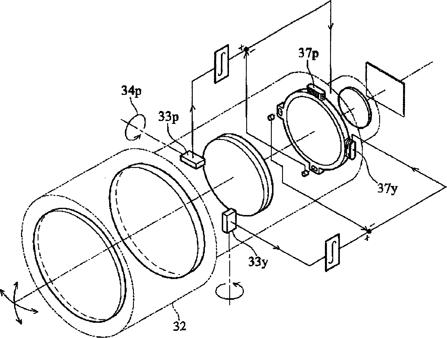
【Technical field】 [0001] The present invention relates to an image sensing module, in particular to an image sensing module that allows the image sensing unit to move in two dimensions. 【Background technique】 [0002] Such as figure 1 As shown, US Patent Publication No. 5266988 discloses an image vibration suppression device for a camera. The image vibration suppression device is arranged in the lens 32. When using the camera, the angular acceleration units 33p, 33y measure the angular acceleration information of the operator's vibrating camera, and provide a circuit to calculate and drive a group of driving components 37p, 37y. The components 37p and 37y move a lens in the lens 32 in the direction perpendicular to the optical axis to correct or suppress image blur caused by the operator vibrating the camera. [0003] However, driving the lenses in the lens to move in the direction perpendicular to the optical axis will reduce the peripheral brightness of the lens, and the...

Claims


Application Information

Patent Timeline
IPC IPC(8): G02B27/64
Inventor 周宗陵贾硕颀吴木源
Owner ASIA OPTICAL CO INC
Learn More