Spinning head and filter device for said type of spinning head

A technology of filter device and spinneret, which is applied in spinneret assembly, spinning solution defoaming, textile and papermaking, etc., can solve the problems such as the inability of the spinning head to establish melt flow and the uneven utilization of filter materials, etc. achieve the effect of improving stability

Inactive Publication Date: 2006-11-15
SAURER GMBH & CO KG
View PDF6 Cites 5 Cited by
  • Summary
  • Abstract
  • Description
  • Claims
  • Application Information

AI Technical Summary

Problems solved by technology

[0006] In the known solutions using shaped filter elements there is also the problem that, due to the shape of the filter element, the flow-through characteristics over the entire surface of the filter element are Different, resulting in preferred flow areas, which lead to uneven utilization of the filter material
At the same time a uniform melt flow cannot be established inside the spinning head

Method used


Image

  • Spinning head and filter device for said type of spinning head
  • Spinning head and filter device for said type of spinning head
  • Spinning head and filter device for said type of spinning head

Examples


Embodiment Construction

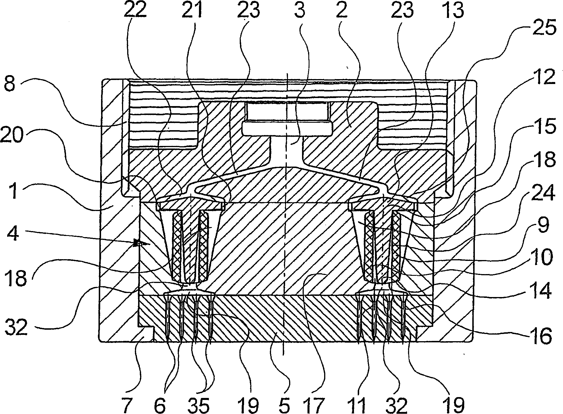
[0025] exist figure 1 A first embodiment of a spinneret according to the invention is schematically shown in longitudinal section. The spinneret has a cylindrical housing 1 . An inner housing flange 7 is formed on the underside of the housing 1 . A spinneret 5 guided inside the housing 1 rests on a housing flange 7 . The spinneret 5 has a plurality of spinneret holes 6 on its bottom side, which are connected to the top side of the spinneret 5 via the spinneret channels 35 .

[0026] An internal thread 8 is formed at the upper end of the housing 1 , via which a feed plate 2 is guided inside the housing 1 . The feed plate 2 has a centrally formed melt inlet 3, which is connected to a melt line (not shown here). The melt inlet 3 is connected to the bottom surface of the feed plate 2 via a feed channel 23 .

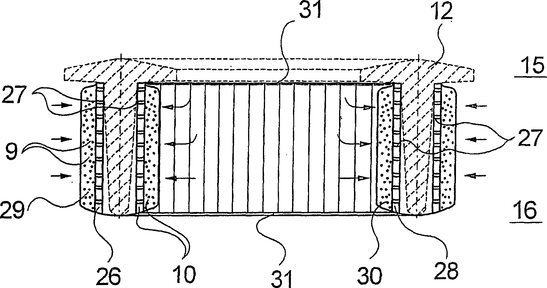
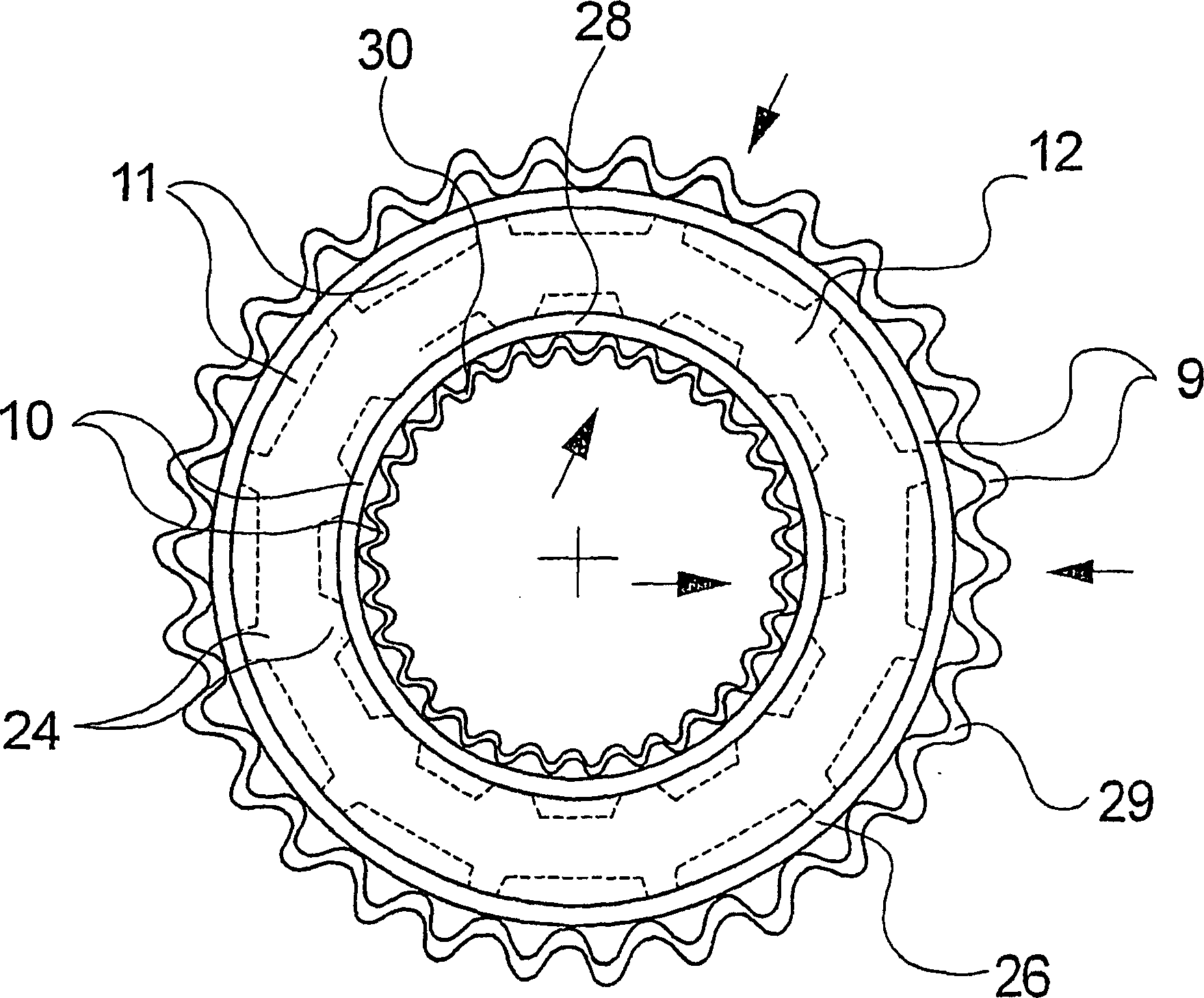
[0027] Between the feed plate 2 and the spinneret 5 , a filter device 4 is formed inside the housing 1 , via which the feed channels 23 formed in the feed plate 2 are co...


PUM


Abstract

The invention relates to a spinning head which is used to melt spin a plurality of synthetic filaments, and to a filter device for said type of spinning head. A filter device is arranged between an inlet plate comprising a melt inlet and a die base comprising several die holes, said filter device comprising a cylindrically-shaped filter ring element which can be cross-flown from the outside to the inside. A separate second filter ring element is associated with the first filter ring element in order to form a sufficient filter surface with large melt through-put rates, said second ring element being arranged at a distance in relation to the outer lying first filter ring element. A first partial flow of the melt is guided through the first filter ring element from the outside to the inside and a second partial flow of the melt is guided through the second filter ring element from the inside to the outside in order to combine them together in a release chamber formed between the filter ring elements.

Description

technical field [0001] The invention relates to a spinneret for melt spinning a plurality of synthetic filaments according to the preamble of claim 1 and to a filter device for a spinneret according to the preamble of claim 12 . Background technique [0002] A spinning head of this type as well as a filter device of this type are known from EP 1 093 535 B1. [0003] When extruding a polymeric melt, the melt is filtered inside the spinneret before passing through a plurality of spinneret holes of a spinneret, for which known spinnerets have a filter device, which consists of a cylindrical filter ring elements. The filter ring element is formed by a support tube and a filter sleeve surrounding the support tube, the support tube and filter sleeve being combined at the support end to form a sealing edge. The filter ring element is fixed in a self-sealing manner within the spinneret by a distribution element, wherein the melt flow is distributed along the circumference of the f...

Claims


Application Information

Patent Timeline
Patent Type & Authority Applications(China)
IPC IPC(8): D01D1/10D01D4/00
CPCD01D1/106D01D4/00
Inventor 安德烈斯·迈斯特凡·贝克尔马库斯·赖希魏因
Owner SAURER GMBH & CO KG
Why Eureka
Try Eureka