Eureka AIR delivers breakthrough ideas for toughest innovation challenges, trusted by R&D personnel around the world.

Three-layer divided-flow hot runner rack

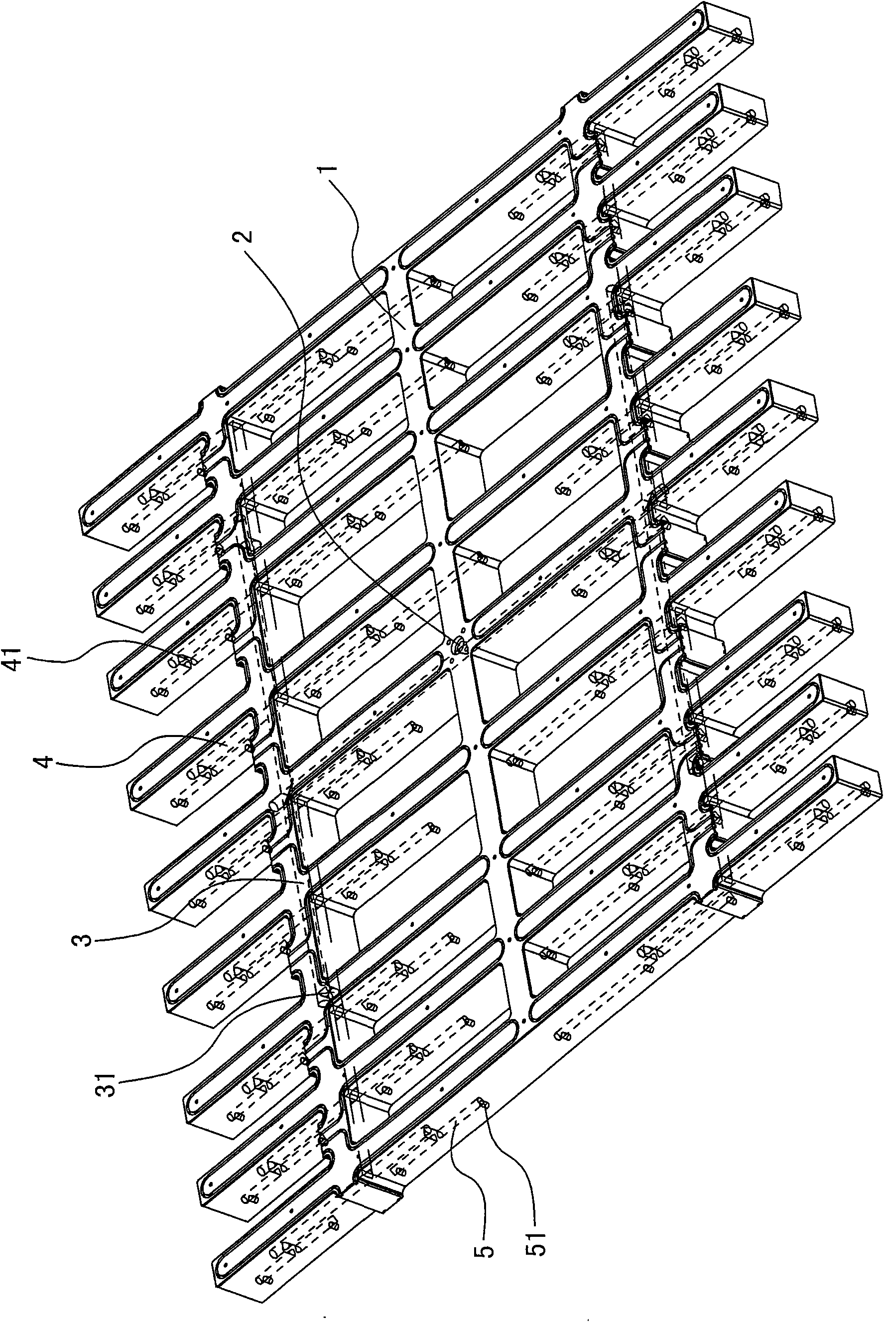
A shunt channel and shunt type technology, applied in the field of three-layer shunt type hot runner rack, can solve the problems of reduced tray strength, short service life, insufficient injection molding, etc., achieve long service life, sufficient injection molding, and ensure flow balance.

Inactive Publication Date: 2010-01-06
浙江荣信模具塑料有限公司
View PDF6 Cites 2 Cited by
  • Summary
  • Abstract
  • Description
  • Claims
  • Application Information

AI Technical Summary

Problems solved by technology

However, in the production process, due to the large area of ​​the tray, the existing tray adopts a single-layer or double-layer shunt structure during injection molding, which may easily cause insufficient injection molding, reduce the strength of the tray, and shorten the service life.

Method used


Image

  • Three-layer divided-flow hot runner rack
  • Three-layer divided-flow hot runner rack

Examples


Embodiment Construction

[0009] The invention relates to a three-layer shunt type hot runner frame, such as figure 1 , figure 2 As shown, it includes a hot runner frame 1, and a main gate 2 is formed in the hot runner frame 1. It is characterized in that the first runner 3, the second runner 4 and the third runner are made in the hot runner frame 1. 5 three-layer runner, the first runner 3 is connected to the main gate 2, the first blanking port 31 is formed in the first runner 3, the first blanking port 31 is connected to the second runner 4, the second runner 4 is formed with a second blanking port 41, the number of the second blanking port 41 is twice or more than the number of the first blanking port 31, the second blanking port 41 is connected to the third runner 5, The third branch channel 5 is formed with discharge openings 51 that are twice or more than the number of the second discharge openings 41 . In this program, the first runner 3, the second runner 4 and the third runner 5 are made i...


PUM


Abstract

The invention relates to a three-layer divided-flow hot runner rack comprising a hot runner rack in which a main gate is arranged. The invention is characterized in that a layer of first runner, a layer of secondary runner and a layer of third runner are arranged in the hot runner rack, wherein the first runner is communicated with the main gate; first blanking holes are arranged in the first runner and are communicated with the secondary runner in which secondary blanking holes are arranged; the secondary blanking holes are twice or more than twice as many as the first blanking holes; the secondary blanking holes are communicated with the third runner; and discharge holes twice or more than twice as many as the secondary blanking holes are arranged in the third runner. The scheme uses the integration of the three layers of runners and the multi-layer hot runner, outlets in the hot runners progressively increase in a ladder form, and the discharge holes of the third runner are uniformly distributed on the lower surface of the hot runner rack, as well as flow is in balance, thereby causing the arrival time of each point position of a product gate to be consistent so as to cause products to reach smoothness, sufficient injection molding, high intensity and long service life.

Description

technical field [0001] The invention relates to a three-layer diversion type hot runner frame of a plastic mold, which is especially suitable for injection diversion of large-area sewage treatment diaphragms or large plastic trays. Background technique [0002] In the process of environmental sewage treatment, filter membranes are needed. The size of the membrane area determines the sewage treatment area, so the membrane area should be made as large as possible. Due to the large area of ​​the diaphragm, and the surrounding walls of the product are thicker and the middle wall is thinner, the flow of the molten plastic in the existing hot runner structure cannot reach a balance when the diaphragm is injected, and insufficient injection molding is prone to occur, resulting in uneven products. On the other hand, with the development of the logistics industry, it is necessary to use large plastic pallets when unloading or storing. Large plastic pallets have a large area and store...

Claims


Application Information

Patent Timeline
IPC IPC(8): B29C45/27
Inventor 胡兆西
Owner 浙江荣信模具塑料有限公司
Why Eureka
Eureka Blog
Learn More