

Apparatus and method for drawing an optical fiber having reduced and low attenuation loss, and optical fiber produced therefrom
- Summary
- Abstract
- Description
- Claims
- Application Information
AI Technical Summary
Benefits of technology
Problems solved by technology
Method used
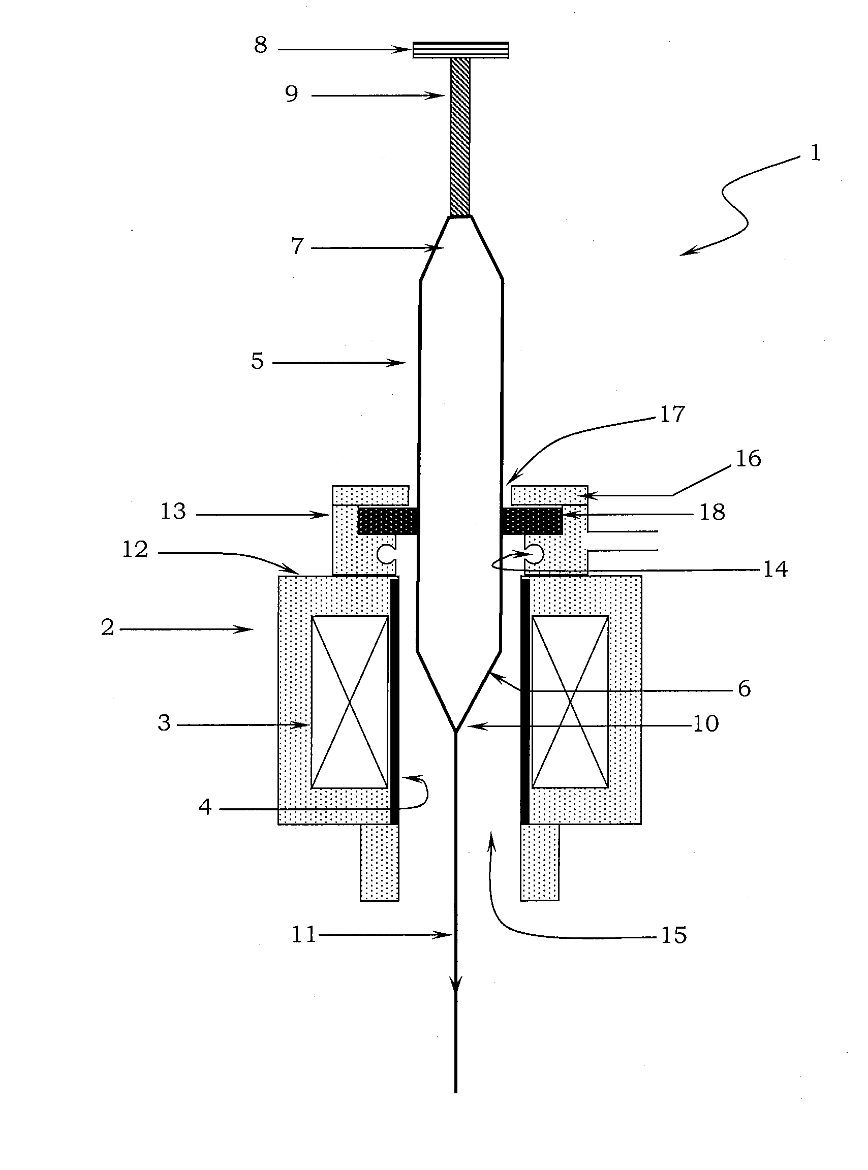
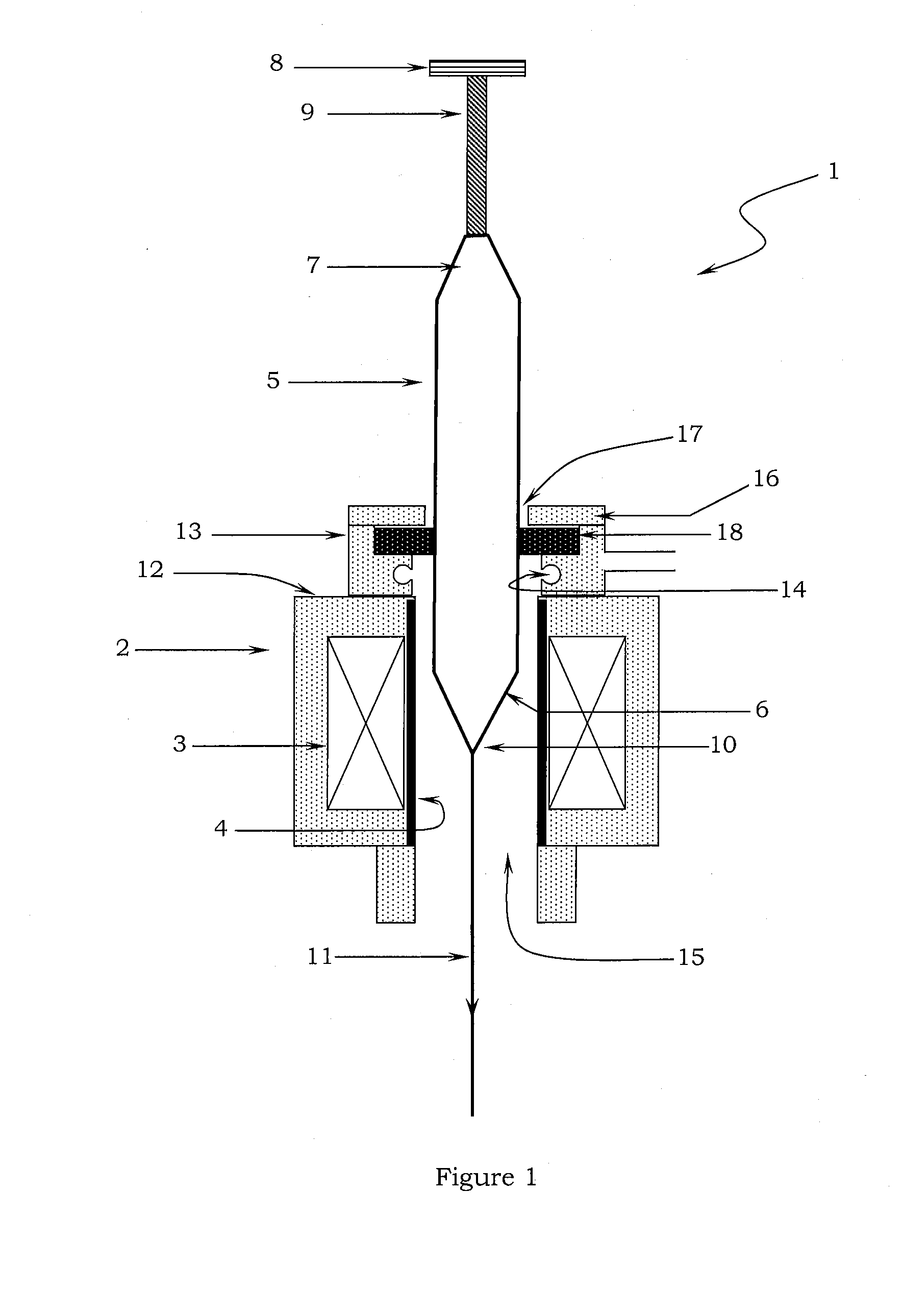
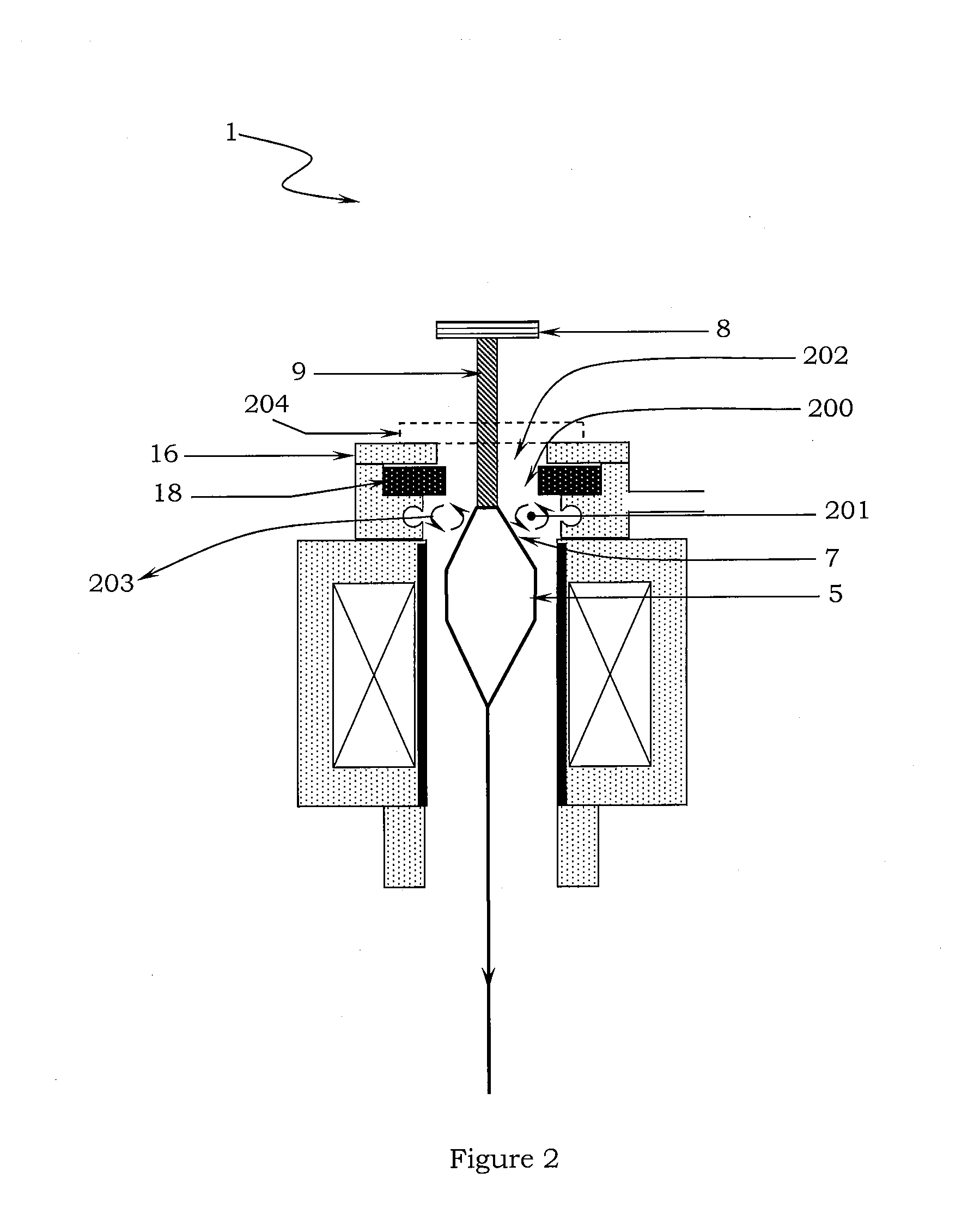
Image

Examples
example 1
Prior Art
[0089] A glass handle of diameter 20 mm as known in art was heat welded to one end of preform of diameter 90 mm and length 70 cm. The assembly of glass handle-optical fiber preform was transferred to the conventional optical fiber drawing furnace and suspended in its core tube by a suspending means. Before suspending the assembly of glass handle-optical fiber preform, a cylindrical tubular member having outer diameter of 90 mm, thickness of 10 mm and height of 20 cm as known in art was positioned on top end of optical fiber preform. Once complete assembly comprising preform, handle and cylindrical member is properly suspended in core tube of furnace, preform heated to a temperature of 2000° C. and fiber drawing is started from bottom end of fiber drawing furnace. A non-contact temperature measuring laser device was used to measure temperature on marked point on surface of cylindrical tubular member from beginning to end of fiber drawing process. The temperature on surface ...
example 2
Embodiment of the Present Invention
[0093] A glass handle of diameter 20 mm as known in art was heat welded to one end of preform of diameter 90 mm and length 70 cm. The assembly of glass handle-optical fiber preform was transferred to the optical fiber drawing furnace of present invention and suspended in its core tube by a suspending means. Before suspending the assembly of glass handle-optical fiber preform, an opaque glass tube non-permeable to IR radiations having outer diameter of 90 mm, thickness of 10 mm and height of 20 cm of the present invention was positioned on top end of optical fiber preform. Once complete assembly comprising preform, handle and opaque glass tube non-permeable to IR radiations is properly suspended in core tube of furnace, preform heated to a temperature of 2000° C. and fiber drawing is started from bottom end of fiber drawing furnace. A non-contact temperature measuring laser device was used to measure temperature on marked point on surface of opaque...
PUM
| Property | Measurement | Unit |
|---|---|---|
| Temperature | aaaaa | aaaaa |
| Temperature | aaaaa | aaaaa |
| Temperature | aaaaa | aaaaa |
Abstract
Description
Claims
Application Information