Machine tool

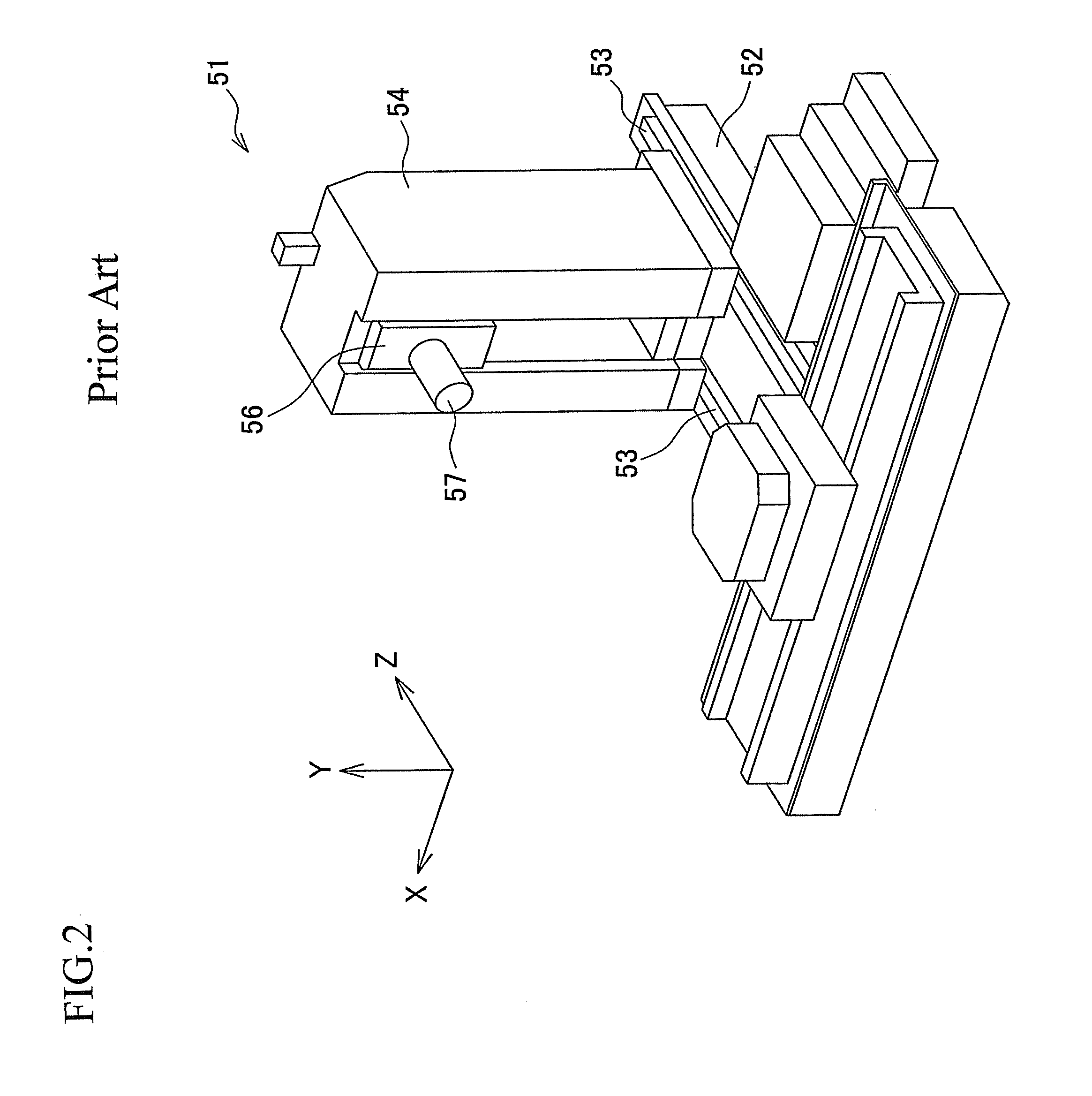
a technology of machine tools and support parts, applied in the field of machine tools, can solve the problems of undesirable increase in the mass of the column, disadvantageous reduction of the structural strength and stability of the column b>54/b>, etc., and achieve the effect of suppressing the structural strength and stability of the support member due to the upward shift of the center of gravity, increasing and reducing the mass of the support member

Active Publication Date: 2014-01-21
OKUMA CORP
View PDF3 Cites 2 Cited by
  • Summary
  • Abstract
  • Description
  • Claims
  • Application Information

AI Technical Summary

Benefits of technology

[0011]According to the above aspect of the present invention, the engageable portion for allowing the support member to be supported by the guide member is located at a level within a range of the upward-downward movement of the headstock along the support member; thus, the support member is supported by the guide member at the level which is higher than that at which a conventional support member (column) is supported by a guide member (a pair of rail members). Therefore, the vertical distance from a position in the support member at which the support member is supported by the guide member to a position of the headstock that has been moved upwardly along the support member in this configuration is shorter than in the conventional configuration. Consequently, undesirable deterioration in the structural strength and stability of the support member due to the upward shift of the center of gravity can be suppressed without any additional measures such as increasing the mass of the support member. Moreover, the mass of the support member can be reduced as compared with the conventional configuration, so that the miniaturization of the machine tool can be achieved. Further, the feed speed, acceleration, deceleration, etc. of the support member can be increased, so that the machining operation can be performed with improved efficiency.
[0012]With the additional feature of the wall portions in the bed as described above, which wall portions are configured to stand upright with a predetermined distance put therebetween, the thickness of the bed in the vertical direction is increased, so that the flexural rigidity of the bed can be increased.

Problems solved by technology

However, the headstock 56 moved upward brings the center of gravity of the column 54 upward accordingly; therefore, the structural strength and stability of the column 54 would disadvantageously be lowered.
This problem may possibly be overcome by providing the column 54 with increased rigidity, but this would create several other problems such as an undesirable increase in the mass of the column 54, upsizing of the machine tool 51 in its entirety, and upsizing of a motor or the like for driving the column 54.

Method used


Image

  • Machine tool
  • Machine tool
  • Machine tool

Examples


Embodiment Construction

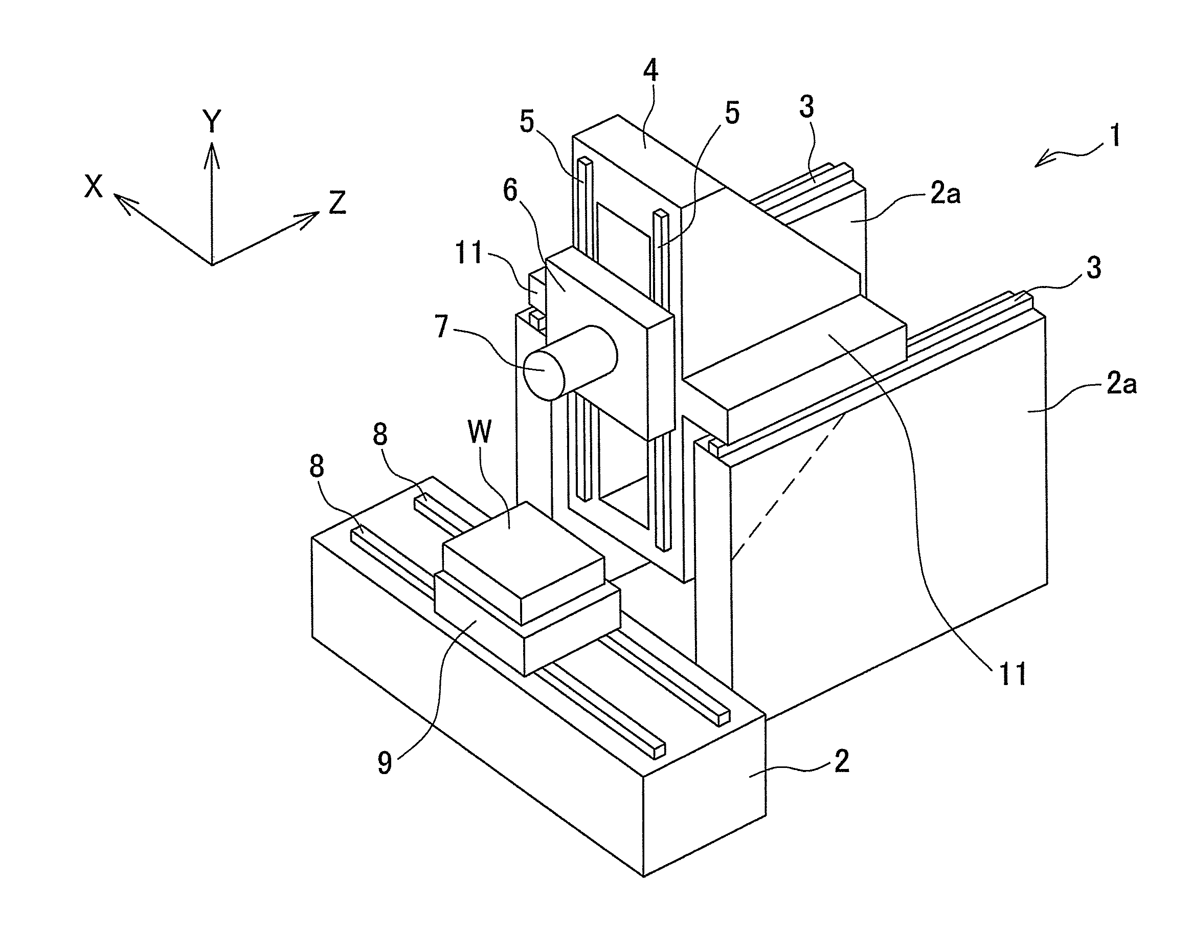
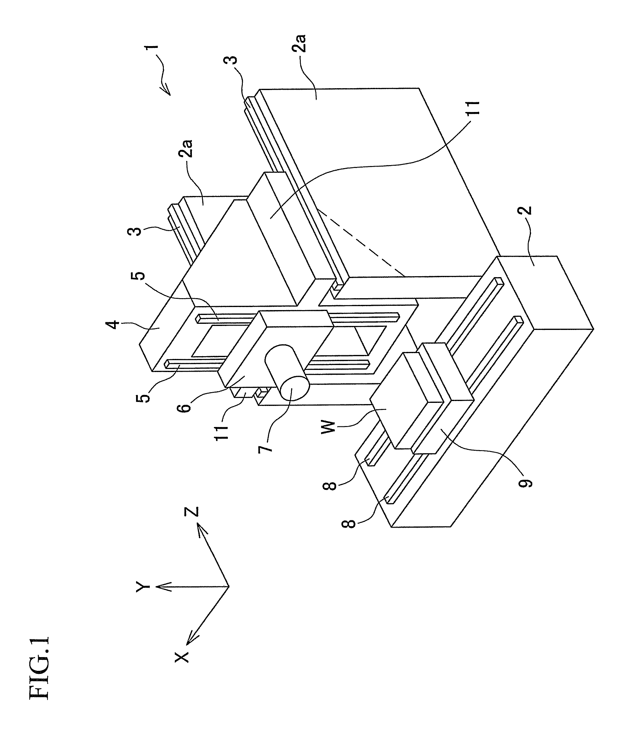
[0016]A detailed description of a machine tool will be given according to an exemplary embodiment of the present invention with reference made to FIG. 1. In this embodiment as well, X axis, Y axis and Z axis are axes perpendicular to one another, and are oriented such that the X axis extends leftward and rightward, the Y axis extends upward and downward, and the Z axis extends frontward and backward; thus, the terms “x-axis direction”, “y-axis direction” and “z-axis direction” are used to designate a leftward-rightward direction, an upward-downward direction and a frontward-backward direction, respectively.

[0017]A machine tool 1 is a device designed specifically for machining of a workpiece W placed on a table 9 by means of a tool installed at a spindle 7. In a bed 2 as a pedestal, a pair of wall portions 2a extending in the z-axis direction are disposed parallel to each other and stand upright with a predetermined distance put therebetween in the x-axis direction. On an upper end f...


PUM

PropertyMeasurementUnit
distanceaaaaaaaaaa
gravityaaaaaaaaaa
structural strengthaaaaaaaaaa

Abstract

In a machine tool, a support member to which a headstock is mounted movably in an upward-downward direction is movable so as to change a position thereof in a horizontal direction relative to that of a bed. A guide member is provided on the bed and configured to guide the support member. An engageable portion at which the support member is supported by the guide member is located in the support member at a level within a range of upward-downward movement of the headstock along the support member.

Description

CROSS-REFERENCE TO RELATED APPLICATIONS[0001]This application claims the entire benefit of Japanese Patent Application Number 2009-207450 filed on Sep. 8, 2009, the entirety of which is incorporated by reference.BACKGROUND OF THE INVENTION[0002]1. Field of the Invention[0003]This invention relates to a machine tool comprising a column which is slidable in a predetermined direction.[0004]2. Description of Related Art[0005]A machine tool including a column slidable in a z-axis direction (i.e., frontward and rearward) on a bed and a headstock translatable in a y-axis direction (i.e., upward and downward) along the column is known in the art (e.g., JP 7-88737 A). Such a machine tool 51 is now described briefly with reference to FIG. 2. In FIG. 2, X axis, Y axis and Z axis are axes perpendicular to one another, and are oriented such that the X axis extends leftward and rightward, the Y axis extends upward and downward, and the Z axis extends frontward and backward; thus, the terms “x-axi...

Claims


Application Information

Patent Timeline
Patent Type & Authority Patents(United States)
IPC IPC(8): E02D5/44
CPCB23Q1/626B23Q1/4819B23Q1/017B23Q1/25Y10T82/2552Y10T408/37Y10T408/91Y10T408/94Y10T409/308288Y10T409/309352Y10T409/309408Y10T409/309576
Inventor YOSHIDA, MAKOTO
Owner OKUMA CORP
Why Eureka
Try Eureka