Variable valve device for internal combustion engine

a valve device and internal combustion engine technology, applied in the direction of braking system, process and machine control, instruments, etc., can solve the problems of achieve successful reduction of pumping losses, prevent deterioration of combustion stability and fuel consumption, and reduce the effect of pumping loss

Active Publication Date: 2011-05-12
MITSUBISHI MOTORS CORP
View PDF2 Cites 0 Cited by
  • Summary
  • Abstract
  • Description
  • Claims
  • Application Information

AI Technical Summary

Benefits of technology

[0010]In the variable valve device for an internal combustion engine, which has the cam phase variable mechanism including a split variable function for varying the phase of the second intake cam relative to the first intake cam, when the operation of the internal combustion engine is in the predetermined extremely low speed and load region, the phase of the second intake cam is controlled to the more advanced position than the phase in which the closing timing of the second intake valve is in the most retarded position. In the extremely low speed and load region, therefore, if the phase of the second intake cam is retarded by the cam ph...

Problems solved by technology

In the extremely low speed and load region, therefore, if the phase of the second intake cam is retarded by the cam phase variable mechanism having the split variable function, it ...

Method used


Image

  • Variable valve device for internal combustion engine
  • Variable valve device for internal combustion engine
  • Variable valve device for internal combustion engine

Examples


Embodiment Construction

[0019]One embodiment of the invention will be described below with reference to the attached drawings.

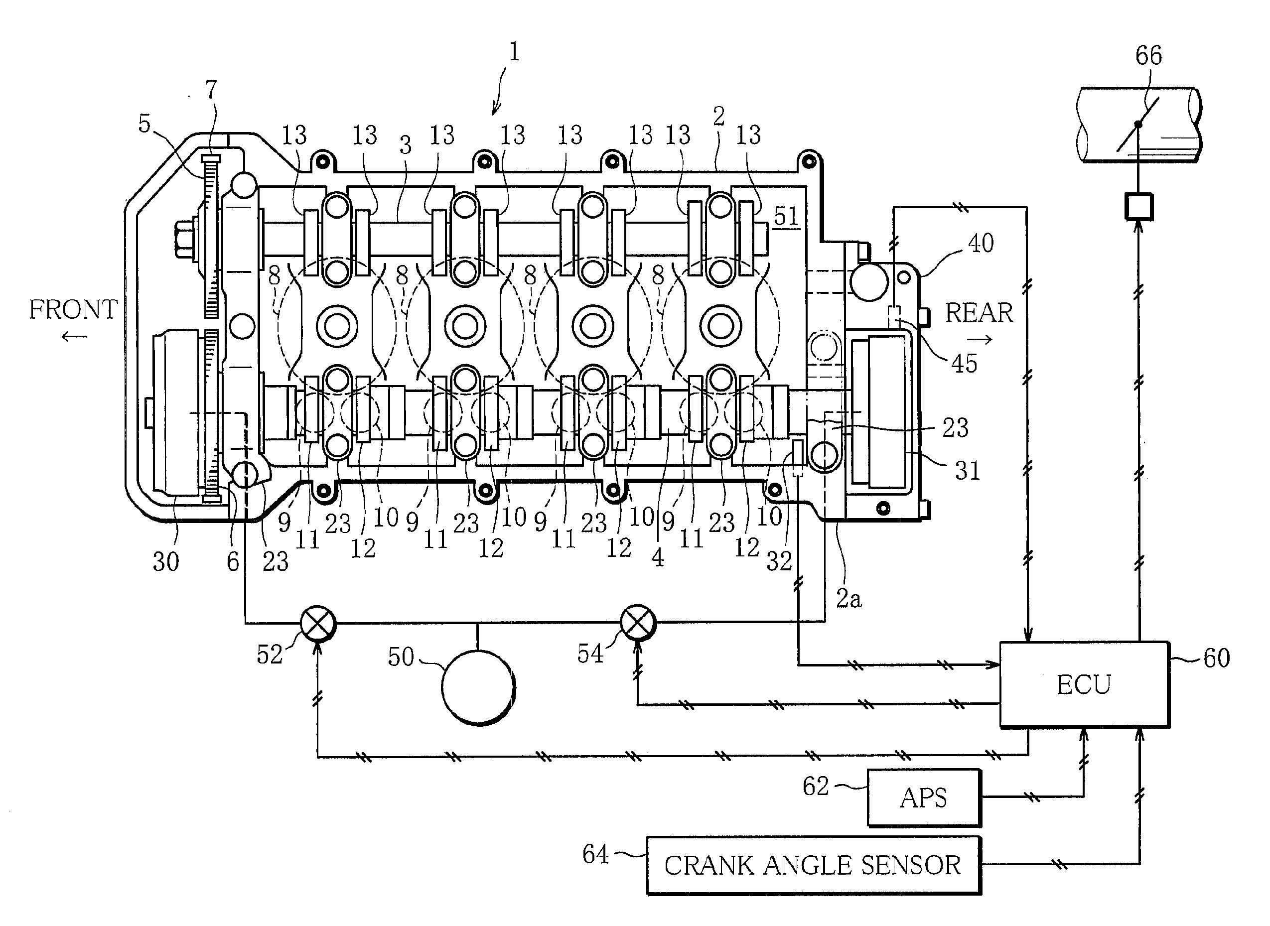
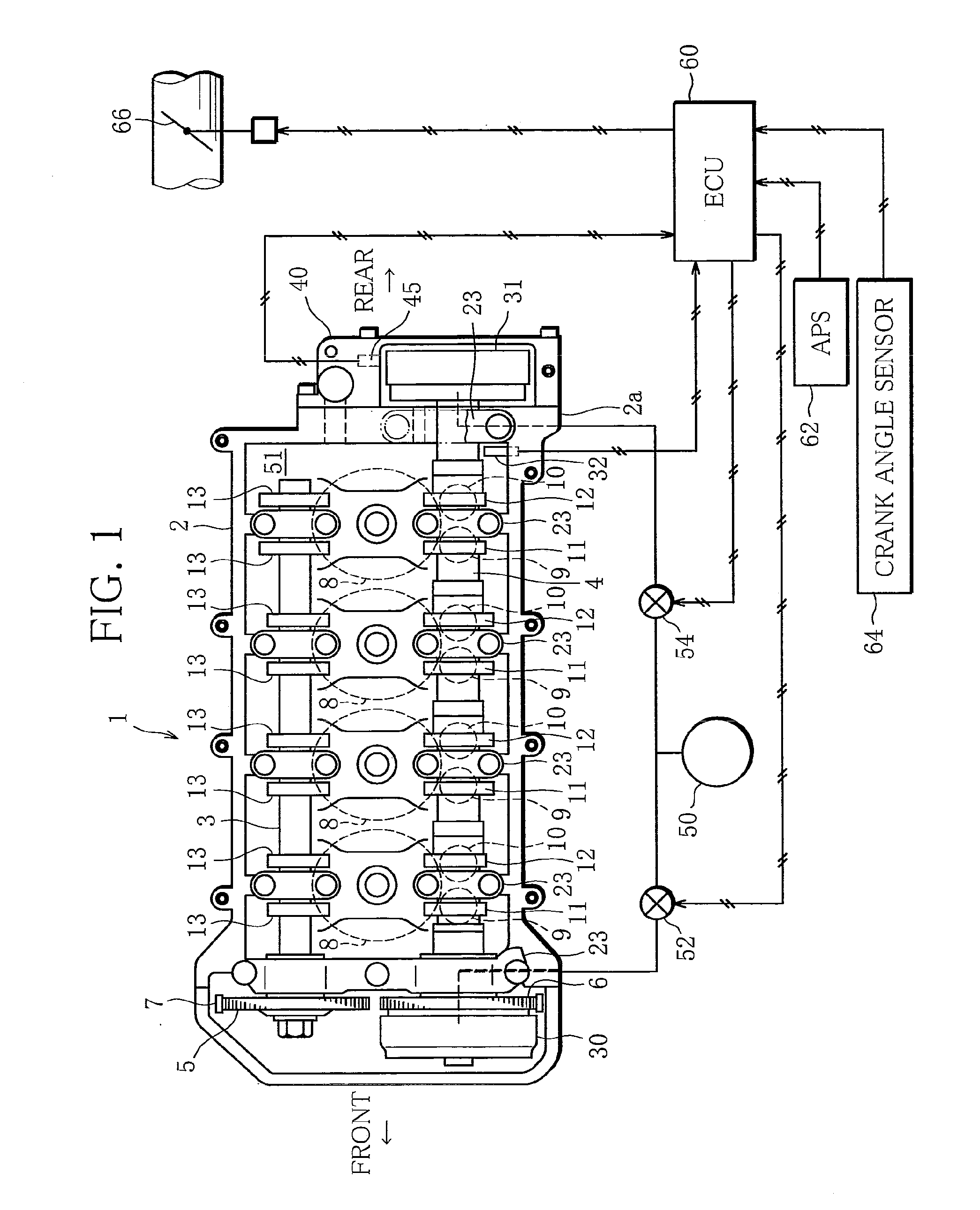
[0020]FIG. 1 schematically illustrates the construction of a variable valve device for an internal combustion engine according to the present invention. More particularly, FIG. 1 is a top view showing the internal structure of a cylinder head 2 of an engine 1.

[0021]The engine 1 is, for example, an in-line four-cylinder engine with a DOHC valve train. As illustrated in FIG. 1, cam sprockets 5 and 6 are connected to an exhaust camshaft 3 and an intake camshaft 4, respectively, which are rotatably supported in the cylinder head 2. The cam sprockets 5 and 6 are interlocked to a crankshaft, not shown, through chains 7.

[0022]Disposed in each cylinder 8 of the engine 1 are two intake valves 9 and 10 and two exhaust valves, not shown. All pairs of intake valves 9 and 10 are driven by first intake cams 11 and second intake cams 12 which are alternately arranged in the intake camshaft 4. More...


PUM


Abstract

In a variable valve device for an internal combustion engine, which has a cam phase variable mechanism including a split variable function, when the operation of the internal combustion engine is in a predetermined extremely low speed and load region, the phase of a second intake cam is controlled to a more advanced position (S1) than the phase in which the closing timing of a second intake valve is in a most retarded position.

Description

BACKGROUND OF THE INVENTION[0001]1. Field of the Invention[0002]The present invention relates to a variable valve device for internal combustion engines, and more particularly, to techniques for optimizing valve opening / closing timings of intake and exhaust valves.[0003]2. Description of the Related Art[0004]In recent years, more and more internal combustion engines (engines) have come to be equipped with cam phase variable mechanisms as a variable valve device for varying valve opening / closing timings (cam phases). Also, techniques have been developed whereby the cam phase variable mechanisms are applied to an engine having each cylinder provided with a plurality of intake valves and the valve opening / closing timings of all intake valves as well as only some of the intake valves are varied (split) in accordance with the operating condition of the engine (Japanese Laid-open Patent Publication No. 2009-144521).[0005]Where the valve opening / closing timings of only some of the intake v...

Claims


Application Information

Patent Timeline
IPC IPC(8): F01L1/344
CPCF01L1/34F01L1/34413F01L2001/0473F01L2800/01Y02T10/142F02D13/0238F02D13/0257F02D13/0269F01L2800/02Y02T10/12
Inventor MURATA, SHINICHI
Owner MITSUBISHI MOTORS CORP
Why Eureka
Try Eureka