Bobbin for winding optical fiber and optical fiber

a technology of optical fiber and winding bobbin, which is applied in the direction of fiber mechanical structure, thin material processing, instruments, etc., can solve the problems of difficult full-automatic winding work, difficult to mechanize or automate work at the start of winding, and negative influence on the transmission loss properties of optical fiber, etc., to achieve low cost and reduce work costs

Active Publication Date: 2016-06-16
THE FUJIKURA CABLE WORKS LTD
View PDF0 Cites 2 Cited by
  • Summary
  • Abstract
  • Description
  • Claims
  • Application Information

AI Technical Summary

Benefits of technology

[0012]The present invention has been made under the above circumstances, and provides a bobbin for winding an optical fiber adapted to be capable of simply and easily introducing an optical fiber, such as an optical fiber, from an auxiliary winding drum to a main winding drum, without generating a crossover wire while avoiding deterioration of the strength or rigidity of a main flange portion caused by the formation of the slit as described above, and thereby capable of mechanizing and automating winding work.
[0024]In the bobbin for winding an optical fiber of the aspects of the present invention, as the shape of the main flange portion for allowing the optical fiber, such as an optical fiber, to ride over the main flange portion between the auxiliary winding drum and the main winding drum and to start winding of the optical fiber onto the main winding drum, a shape capable of preventing generation of a crossover wire without causing deterioration of the strength or rigidity of the main flange portion and easily allowing the optical fiber to ride over the main flange portion without depending on manual work is applied.
[0026]Additionally, according to the bobbin for winding an optical fiber of the present invention, winding work can be fully automated without the properties of the optical fiber deteriorating, and costs of work can be reduced and as a result an optical fiber product in which the optical fiber is wound around the bobbin can be manufactured at low cost.

Problems solved by technology

Therefore, there is a negative influence on these transmission loss properties of the optical fiber.
Therefore, it is very difficult to mechanize or automate work at the start of winding.
Therefore, full-automation of winding work is difficult, and there are also limitations to increasing efficiency of work, and cost reduction.
Therefore, when the optical fiber is wound or delivered while rotating the bobbin at a high speed, there is a concern that the main flange portion and its root portion may be damaged.
Particularly, in recent years, since an optical fiber wound around a bobbin also becomes lengthy and a force applied to the main flange portion becomes large, there has been a high possibility of the main flange portion being damaged.
Additionally, if the slit as described above is provided in the main flange portion, when the bobbin around which the optical fiber is already wound is gripped by hand or the like for transfer and the like, the main flange portion may warp due to insufficient rigidity and collapse (winding collapse) of an optical fiber winding layer may occur.
In addition, although the deterioration in the strength or rigidity of the main flange portion accompanying the formation of the slit can be compensated for by reinforcing the main flange portion with ribs and the like, there are also limitations to this compensation.
Therefore, it is difficult to reliably prevent damage to the above main flange portion, and the weight of the bobbin increases or costs of materials also rise.

Method used


Image

  • Bobbin for winding optical fiber and optical fiber
  • Bobbin for winding optical fiber and optical fiber
  • Bobbin for winding optical fiber and optical fiber

Examples


Embodiment Construction

[0049]Hereinafter, embodiments of the present invention will be described in detail.

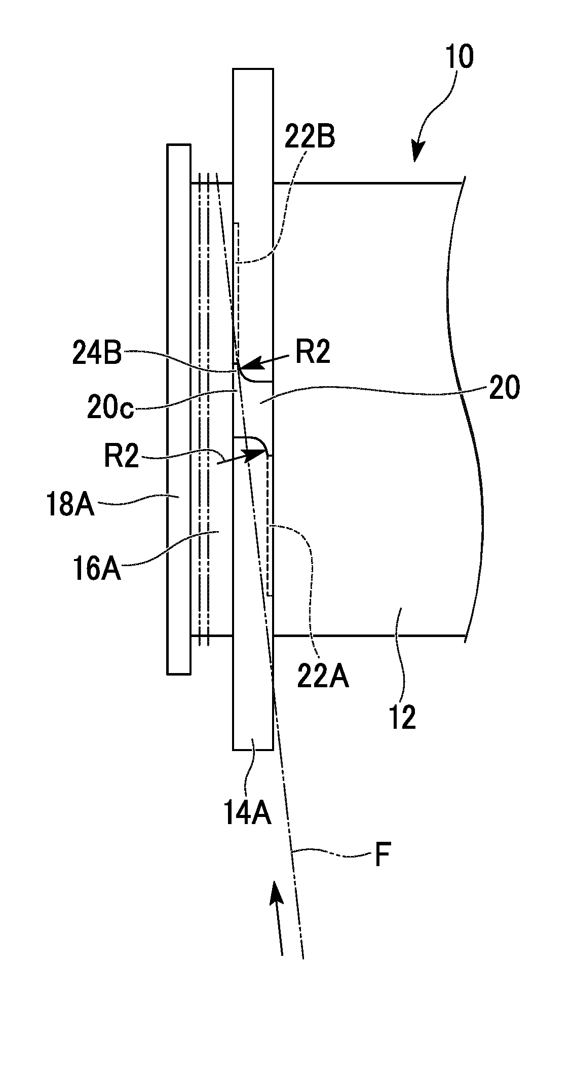
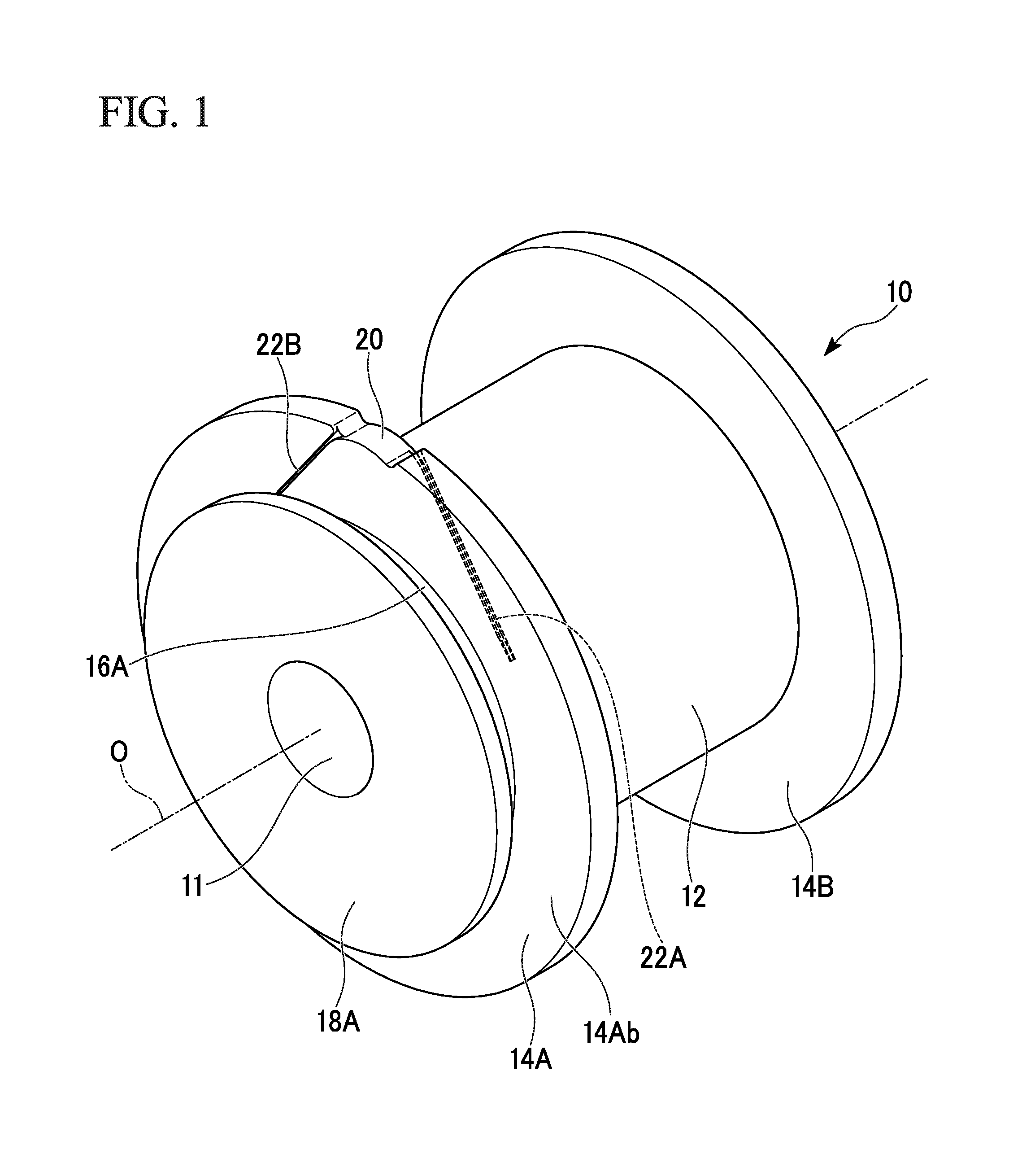
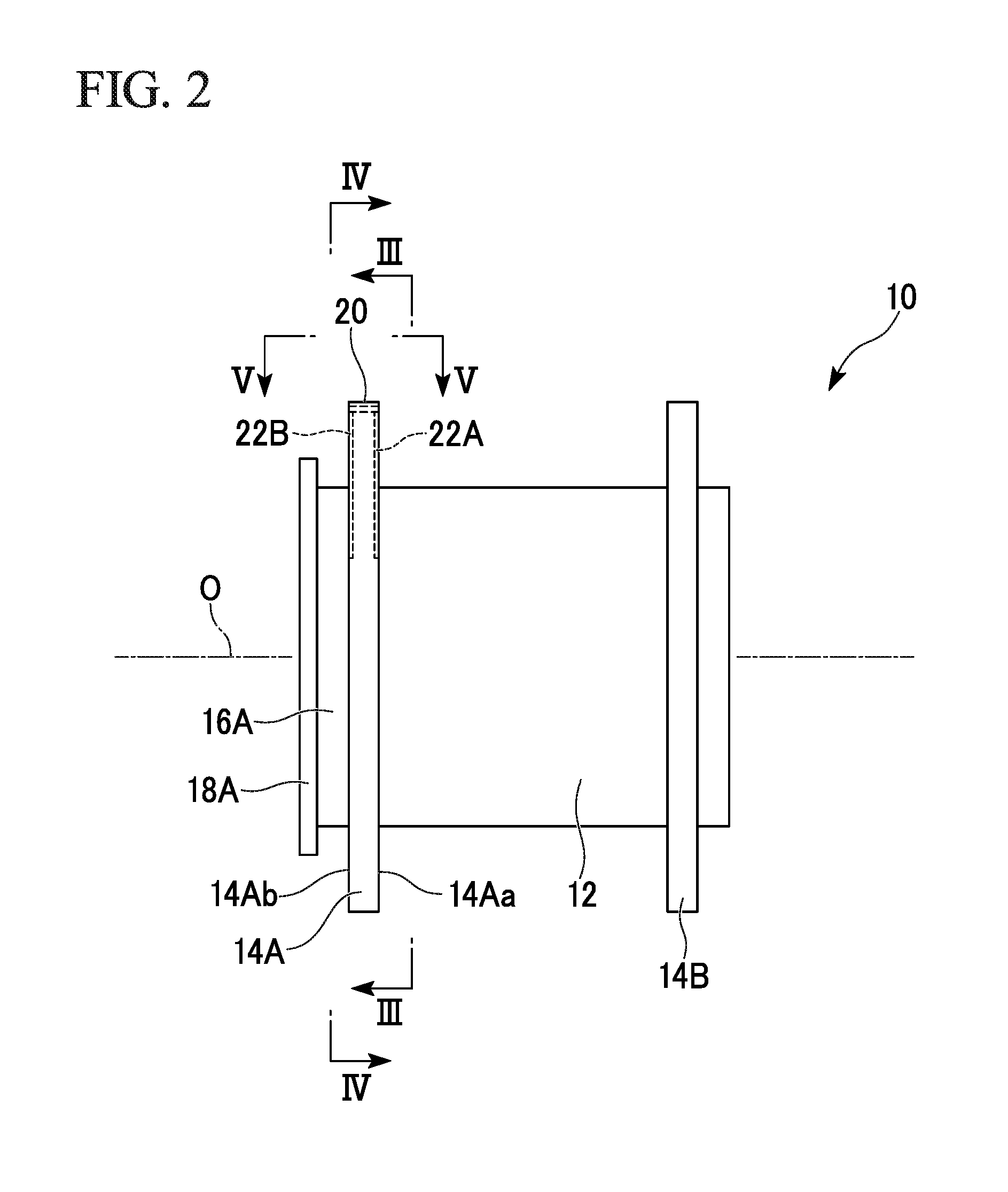
[0050]A bobbin for winding an optical fiber related to an embodiment of the present invention is shown in FIGS. 1 and 2, and main portions of the bobbin of the embodiment are shown in an enlarged manner in FIGS. 3 to 8. In addition, the bobbin for winding an optical fiber related to the embodiment of the present invention is mainly used in order to wind a fiber in which an optical fiber in an element wire state, that is, an optical fiber bare wire having a core and cladding is covered with a protective covering layer. In the following descriptions, an object to be wound will be described as an optical fiber. However, the bobbin of the present invention may also be used for linear objects other than the optical fiber.

[0051]In FIGS. 1 to 8, in a bobbin 10, basically, similar to a related-art bobbin, flange portions 14A and 14B with a larger diameter than the external diameter of a main winding drum 12 ...


PUM


Abstract

A bobbin for winding an optical fiber includes a main winding drum having a cylindrical shape, an auxiliary flange portion that is provided on at least one of a first end and a second end of the main winding drum in an axis direction of the main winding drum, a first main flange portion that has a larger diameter than the external diameter of the auxiliary flange portion and that is provided on the main winding drum to face the auxiliary flange portion, a second main flange portion that is provided on the main winding drum to face the first main flange portion, and an auxiliary winding drum that is provided between the first main flange portion and the auxiliary flange portion.

Description

CROSS REFERENCE TO RELATED APPLICATIONS[0001]This application is a continuation application based on a PCT Patent Application No. PCT / JP2014 / 072772, filed Aug. 29, 2014, whose priority is claimed on Japanese Patent Application No. 2013-179397 filed Aug. 30, 2013, the entire contents of which are hereby incorporated by reference.BACKGROUND OF THE INVENTION[0002]1. Field of the Invention[0003]The present invention relates to a bobbin for winding optical fibers, such as an optical fiber for communication. Particularly, the present invention relates to a bobbin that is suitable for allowing an optical fiber to ride over a flange portion from an auxiliary winding drum and winding the optical fiber around a main winding portion as a bobbin having the auxiliary winding drum at the end portion, and an optical fiber wound around the bobbin.[0004]2. Description of the Related Art[0005]Bobbins in which flange portions are provided at both ends of a winding drum (a main winding drum to be descr...

Claims


Application Information

Patent Timeline
Patent Type & Authority Applications(United States)
IPC IPC(8): B65H75/14G02B6/44B65H75/28
CPCB65H75/146B65H2701/32G02B6/4457B65H75/285B65H75/14B65H75/28
Inventor SHIRAKO, YUKINARIVASUDEVAN, BALASUBRAMANIAMTANAKA, KOHEISAITO, KAZUNARI
Owner THE FUJIKURA CABLE WORKS LTD
Why Eureka
Try Eureka