Data storage device and suspension

a data storage device and suspension technology, applied in the field of suspension and data storage devices, can solve the problems of obstructing the accuracy of the track following operation, deteriorating the reliability of the hdd, and narrow pitch, so as to suppress the deterioration of rigidity and dynamic characteristics, enhance the reliability of the data storage device, and reduce power consumption

Active Publication Date: 2005-10-06
WESTERN DIGITAL TECH INC
View PDF6 Cites 2 Cited by
  • Summary
  • Abstract
  • Description
  • Claims
  • Application Information

AI Technical Summary

Benefits of technology

[0022] A data storage device in accordance with a third aspect of the present invention comprises a recording disk adapted to store data and rotate, a head adapted to access a recording area on the recording disk which is rotating, a ramp spaced away from an outer peripheral end of the recording disk and to which the head retracts from a position above a surface of the recording disk, a suspension having a deformable gimbals which holds the head and a load beam which holds the gimbals, the suspension being adapted to pivot in a pivotal direction around a pivot shaft, thereby causing the head to move to a position above the surface of the recording disk and to the ramp, and a drive unit for driving the suspension pivotally. The load beam includes a tab extending from a central part in the pivotal direction of a front end of the load beam and being bent in its section in the pivotal direction, the tab being adapted to slide on a surface of the ramp, flanges formed by bending both longitudinally extending edge portions of the load beam, a first aperture formed in a position overlapping an end face on the tab side of the head, a second aperture formed on the tab side of the first aperture, and a bridge portion formed between the first and second apertures to separate the first and second apertures from each other. Since the ramp is spaced away from the recording disk, it is possible to decrease the power consumption. Moreover, since the load beam has the above construction, it is possible to suppress the deterioration of rigidity and dynamic characteristics.
[0023] According to the present invention, it is possible to provide a suspension structure which permits an assembling process capable of enhancing the reliability of a data storage device and which suppresses the deterioration in rigidity and dynamic characteristics of a head supporting structure.

Problems solved by technology

This is because dust produced at the time of assembling the ramp or the actuator is apt to be deposited on the magnetic disk and causes deterioration in reliability of the HDD.
With the recent increase of the recording density, the track pitch is becoming more and more narrow and therefore a large torsional oscillation component obstructs an accurate track following operation.
As the reason therefor, the same literature states that, to dispose the ramp outside the magnetic disk, it is necessary to form the tab long enough to project from the outer periphery of the magnetic disk, and that the long tab causes deterioration of impact resistance when the device is subjected to a shock.

Method used


Image

  • Data storage device and suspension
  • Data storage device and suspension
  • Data storage device and suspension

Examples


Embodiment Construction

[0034] Embodiments to which the present invention is applicable will be described hereinunder. The following description is for explanation of the embodiment and the present invention is not limited to the following embodiment. For the clarification of explanation, omissions and simplifications will be made as necessary in the following description and the accompanying drawings. It is easy for any person skilled in the art to make changes, additions and conversions of elements in the following embodiment within the scope of the present invention. In the accompanying drawings, the same elements are identified by the same reference numerals, and tautological explanations will be omitted as necessary for the clarification of explanation.

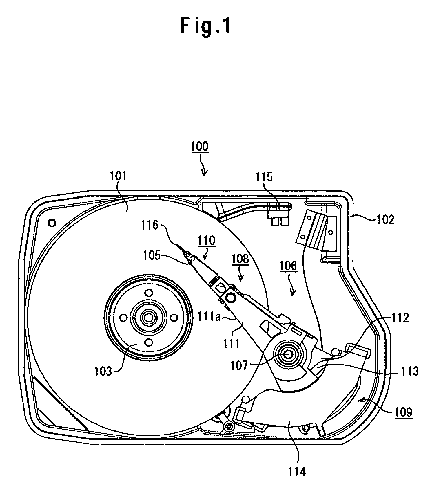
[0035]FIG. 1 illustrates a schematic construction of a hard disk drive (HDD) 100 according to an embodiment of the present invention. In the HDD 100 shown in FIG. 1, an actuator is in operation. In the same figure, the numeral 101 denotes a data record...


PUM

PropertyMeasurementUnit
storage areaaaaaaaaaaa
areaaaaaaaaaaa
elastic forceaaaaaaaaaa

Abstract

A magnetic disk drive is to be provided wherein a ramp and a magnetic disk do not overlap each other and both rigidity and dynamic characteristics of a suspension are maintained. In one embodiment, a ramp and an actuator lying at a retractive position are spaced away from and do not overlap an outer peripheral end of a magnetic disk. A tab is formed centrally of a front end of a load beam and is bent in U shape. Flanges are formed along both longitudinal edges of the load beam. An aperture is formed in a front portion of the load beam. The aperture permits the tab to be machined in a desired shape. An aperture is formed behind the aperture. The aperture is used to clamp a head in a wire bonding step for the head. The apertures and are not formed in an integrally contiguous manner but are separated from each other by a bridge portion.

Description

CROSS-REFERENCES TO RELATED APPLICATIONS [0001] This application claims priority from Japanese patent application No. JP 2004-103832, filed Mar. 31, 2004, the entire disclosure of which is incorporated herein by reference. BACKGROUND OF THE INVENTION [0002] The present invention relates to a suspension and a data storage device using the suspension. Particularly, the present invention is concerned with a suspension and a data storage device suitable for a hard disk drive of a load / unload type. [0003] Devices using various types of media such as optical disks and magnetic tapes are known as data storage devices. Among them, hard disk drives (HDD) have become popular as storage devices for computers to such an extent that they are one of the storage devices indispensable for today's computer systems. Further, not limited to computer systems, the application of the HDDs is widening more and more due to the superior characteristics with the advent of moving picture recording / reproducing...

Claims


Application Information

Patent Timeline
Patent Type & Authority Applications(United States)
IPC IPC(8): G11B21/21G11B5/48
CPCG11B5/4826G11B5/486
Inventor SUZUKI, KOHICHITSUDA, SHINGOOHTA, MUTSUROTSUCHIDA, HIROYASUAOYAGI, AKIHIKO
Owner WESTERN DIGITAL TECH INC
Why Eureka
Try Eureka