Chemical etch assisted spark machining head

A technology of chemical etching and processing heads, which is applied in the direction of electrochemical processing equipment, metal processing equipment, manufacturing tools, etc., can solve the problems of not very convenient, waste of electrolyte, etc., to reduce the risk of sputtering and maximize the flexibility of use Effect

Inactive Publication Date: 2006-11-22
ASULAB SA
View PDF1 Cites 2 Cited by
  • Summary
  • Abstract
  • Description
  • Claims
  • Application Information

AI Technical Summary

Problems solved by technology

This solution is also not very convenient as it would waste electrolyte during the relative movement of the glass plate with respect to the counter electrode

Method used


Image

  • Chemical etch assisted spark machining head
  • Chemical etch assisted spark machining head
  • Chemical etch assisted spark machining head

Examples


Embodiment Construction

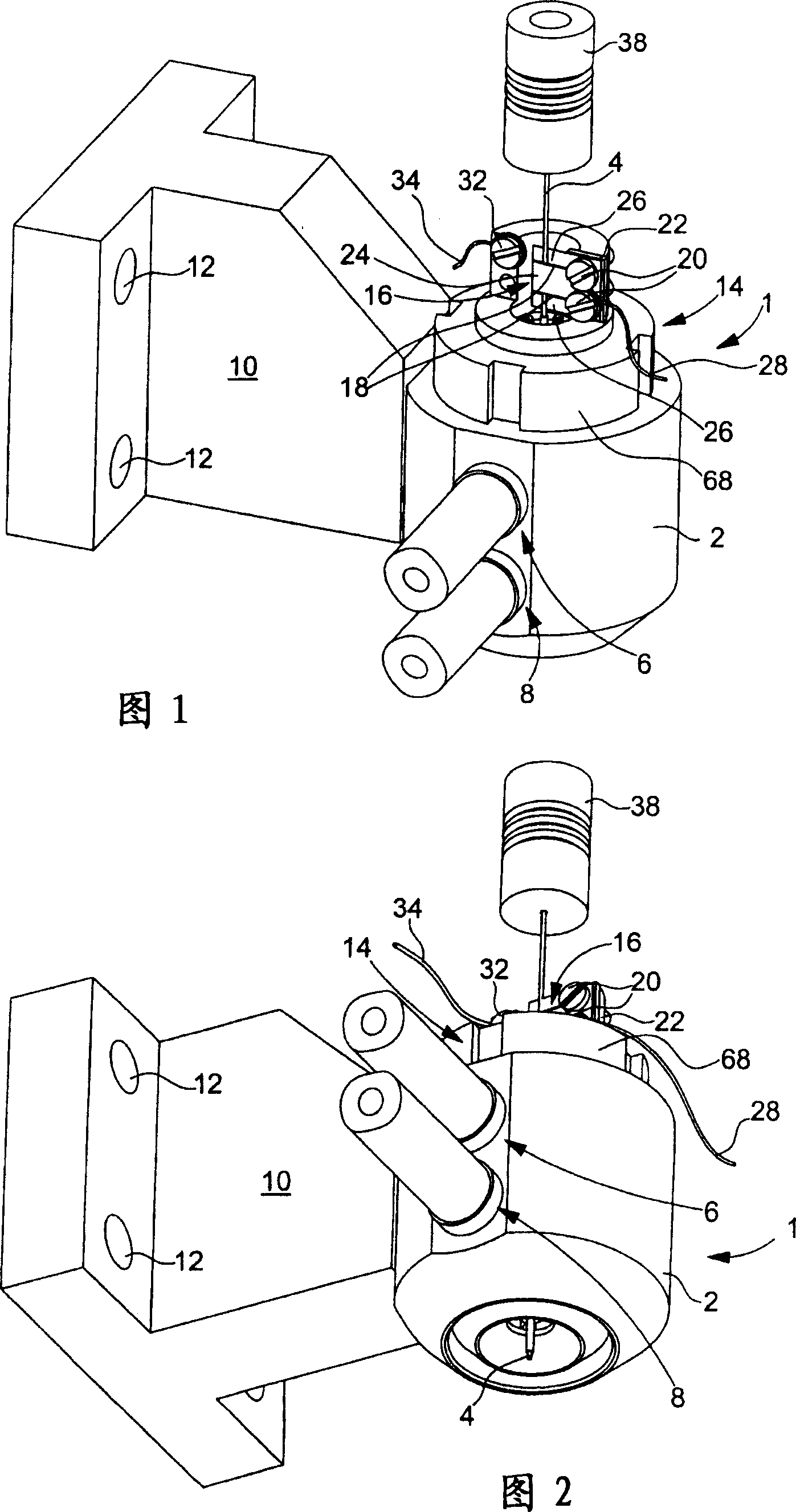
[0024] The present invention stems from the general inventive idea of ​​providing a chemically etch-assisted EDM head capable of three-dimensional movement that can machine large glass sheets with ease, accuracy, and at speeds compatible with industrial-scale production. Furthermore, in a preferred variant of the invention, the processing head is provided with means for supplying and discharging electrolyte, which allows the amount of electrolyte used to be reduced and avoids any risk of electrolyte sputtering.

[0025] The invention will now be described with reference to the machining of holes or cavities in glass sheets. Of course, the invention is not limited to this material, and the invention can be applied to drill holes in any type of non-conductive material such as plastic material, ceramic or semiconductor material.

[0026] Figures 1 and 2 attached hereto show a machining head according to the invention, generally designated by the general reference numeral 1 . The...


PUM

PropertyMeasurementUnit
diameteraaaaaaaaaa

Abstract

The present invention concerns a chemical etch assisted spark machining head, characterized in that it includes a body through which an electrode extends and which defines a counter-electrode extending radially around the electrode, said body including means for feeding an electrolytic liquid into the space delimited by the electrode and the counter-electrode.

Description

technical field [0001] The invention relates to a chemical etching auxiliary electric spark machining head. The present invention particularly relates to a machining head for machining holes in non-conductive materials such as glass sheets. Background technique [0002] In 1968, it was first disclosed to drill small diameter holes in glass sheets using electrical discharge generated by an electrochemical reaction in an electrolyte. This known method has been improved since then. Currently, the method consists in immersing the glass sheet to be processed in a 30% strength electrolytic bath formed, for example, of caustic soda NaOH. A constant voltage, typically between 25V and 40V, is applied between the etching tool forming the cathode and the anode counter electrode in contact with the electrolyte but at a distance from the working area. The hydrogen bubbles formed on the etching tool are concentrated by coalescence and form a gas film covering the electrodes. The disch...

Claims


Application Information

Patent Timeline
Patent Type & Authority Applications(China)
IPC IPC(8): B23H3/00
CPCB23H5/02B23H9/00C25F7/00
Inventor G·雷-梅尔梅特
Owner ASULAB SA
Why Eureka
Try Eureka