Display device and display system
A technology of display devices and substrates, applied in stereoscopic systems, instruments, electrical components, etc., can solve problems such as narrowing user choices and failure to view normally, and achieve the effect of high flexibility of use
- Summary
- Abstract
- Description
- Claims
- Application Information
AI Technical Summary
Problems solved by technology
Method used
Image
Examples
Embodiment 1
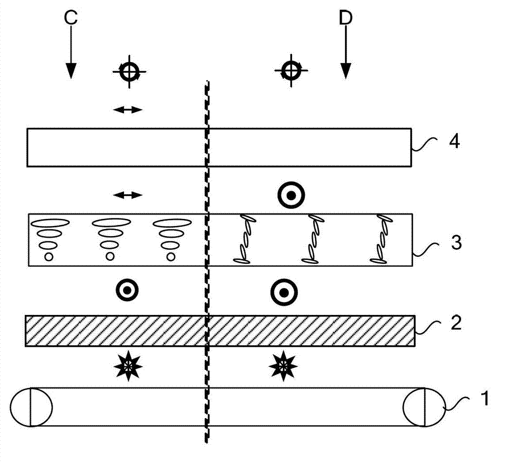
[0051] An embodiment of the present invention provides a display device, such as image 3 As shown, it includes: a frame and a liquid crystal panel located in the frame, the liquid crystal panel has a first substrate, a second substrate and a liquid crystal layer 3 between the first substrate and the second substrate, and the side of the first substrate away from the liquid crystal layer 3 with polarizer 2; also includes:
[0052] The analyzer 4 is movably arranged on the side of the second substrate away from the liquid crystal layer 3 .
[0053] The polarizer 4 has a polarizing function, and can be movably arranged on the side of the second substrate away from the liquid crystal layer 3. That is, when the display device needs to display normally, the polarizer 4 is located on the side of the second substrate away from the liquid crystal layer 3. The polarizer 4 cooperates with the polarizer 2 to display a normal picture; when the display device needs to be kept secret, the ...
Embodiment 2
[0058] Such as Figure 4 As shown, further, the display device provided by this embodiment also includes a fixing mechanism, which is used to detachably install the polarizer 4 on the display device, so that the display device can be displayed between the normal display screen and the abnormal display screen. convert.
[0059] The above-mentioned fixing mechanism can have various structures, and the fixing structure is not necessarily fixed on the display device, as long as the analyzer 4 can be fixed on the display device, the structure of the fixing mechanism listed here is only a part of the structure , not all structures.
[0060] structure one
[0061] Such as Figure 4 As shown, the above-mentioned fixing mechanism is: a mounting groove 51 provided on any two opposite sides of the outer frame 5 and allowing the polarizer to be embedded, at least one of the two mounting grooves 51 is a through groove. The two installation grooves 51 can be arranged on the left and rig...
Embodiment 3
[0077] Such as Figure 9 As shown, the analyzer provided in this embodiment includes: a first transparent electrode layer 81, a polarizing layer having a liquid crystal material and a dichroic dye, and a second transparent electrode layer 82 arranged in sequence;
[0078] When no voltage is applied to the first transparent electrode layer 81 and the second transparent electrode layer 82, the liquid crystal molecules 83 and the dichroic dye molecules 84 in the polarizing layer are all aligned horizontally;
[0079] When the first transparent electrode layer 81 and the second transparent electrode 82 are pressurized, the orientations of the liquid crystal molecules 83 and the dichroic dye molecules 84 in the polarizing layer are all along the direction of the electric field.
[0080] The dichroic dye mainly selectively absorbs polarized light (functions as a polarizer), and deflects along with the polarization of the liquid crystal molecules 83 . The deflection of the liquid cr...
PUM
 Abstract
Description
Claims
Application Information
 - R&D
- Intellectual Property
- Life Sciences
- Materials
- Tech Scout
- Unparalleled Data Quality
- Higher Quality Content
- 60% Fewer Hallucinations
Browse by: Latest US Patents, China's latest patents, Technical Efficacy Thesaurus, Application Domain, Technology Topic, Popular Technical Reports.
© 2025 PatSnap. All rights reserved.Legal|Privacy policy|Modern Slavery Act Transparency Statement|Sitemap|About US| Contact US: help@patsnap.com


