

Aligning-positioning mechanism and aligning-positioning method
一种定位机构、定位构件的技术,应用在定位装置、金属加工机械零件、夹固等方向,能够解决工作周期长、调整工作困难等问题,达到容易调整的效果
- Summary
- Abstract
- Description
- Claims
- Application Information
AI Technical Summary
Problems solved by technology
Method used
Image

Examples
Embodiment Construction
[0034] Embodiments of the present invention are described below with reference to the drawings.
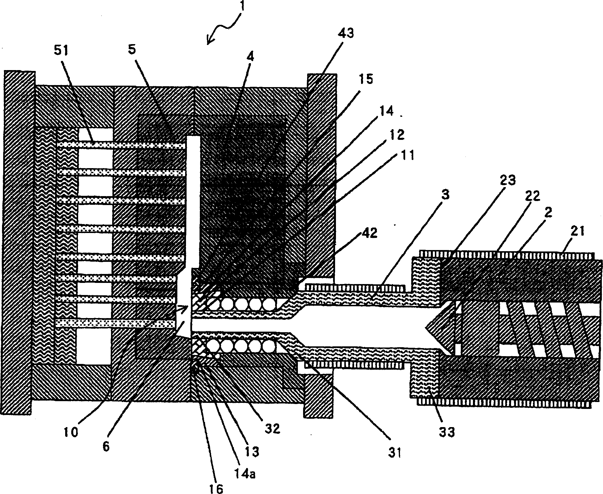
[0035] figure 1 To illustrate a side sectional view of the configuration of a metal injection molding machine and a stationary die, one embodiment of the present invention is applied to this configuration.
[0036] [Metal Injection Molding Machine]
[0037] The metal injection molding machine includes: a heating cylinder 2 having a heater 21 disposed on its outer circumference; an extended nozzle 3 mounted on a front end portion 23 of the cylinder so that it can be inserted into a die; The screw rod 22 inside the barrel 2. The extension nozzle 3 includes: a front end portion 32 fitted in the inner disc hole 11 of the inner disc 12 described later; a mounting end 33 mounted adjacent to the cartridge front end portion 23; and a mounting end 33 formed between the front end portion 32 and the mounting end 33 Tapered portion 31 .
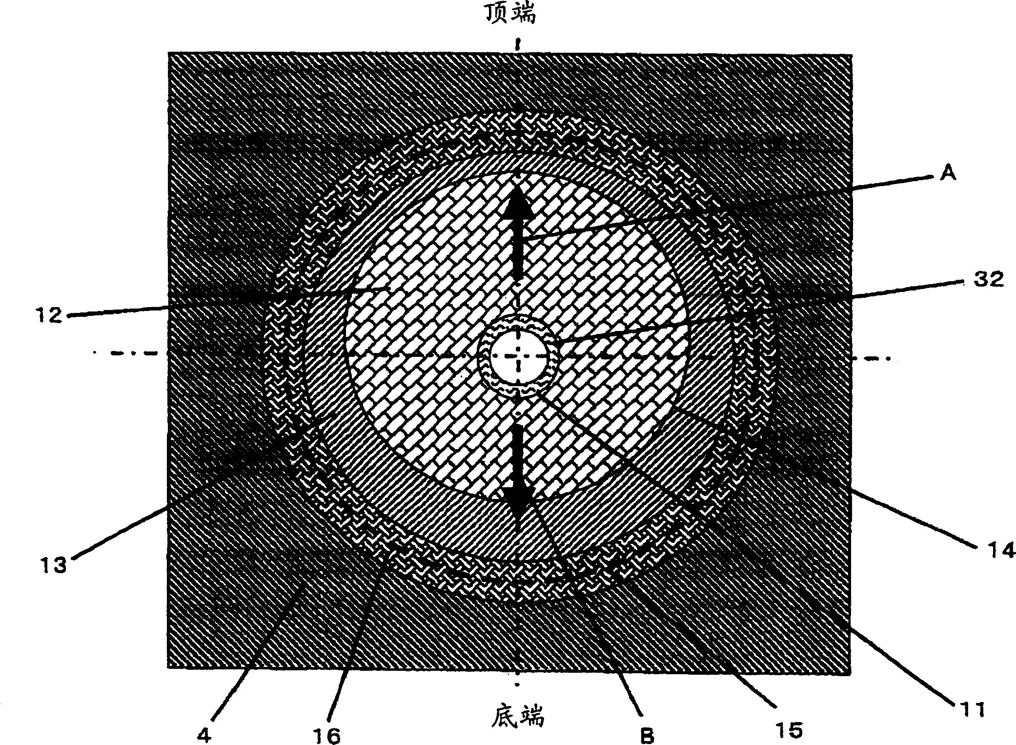
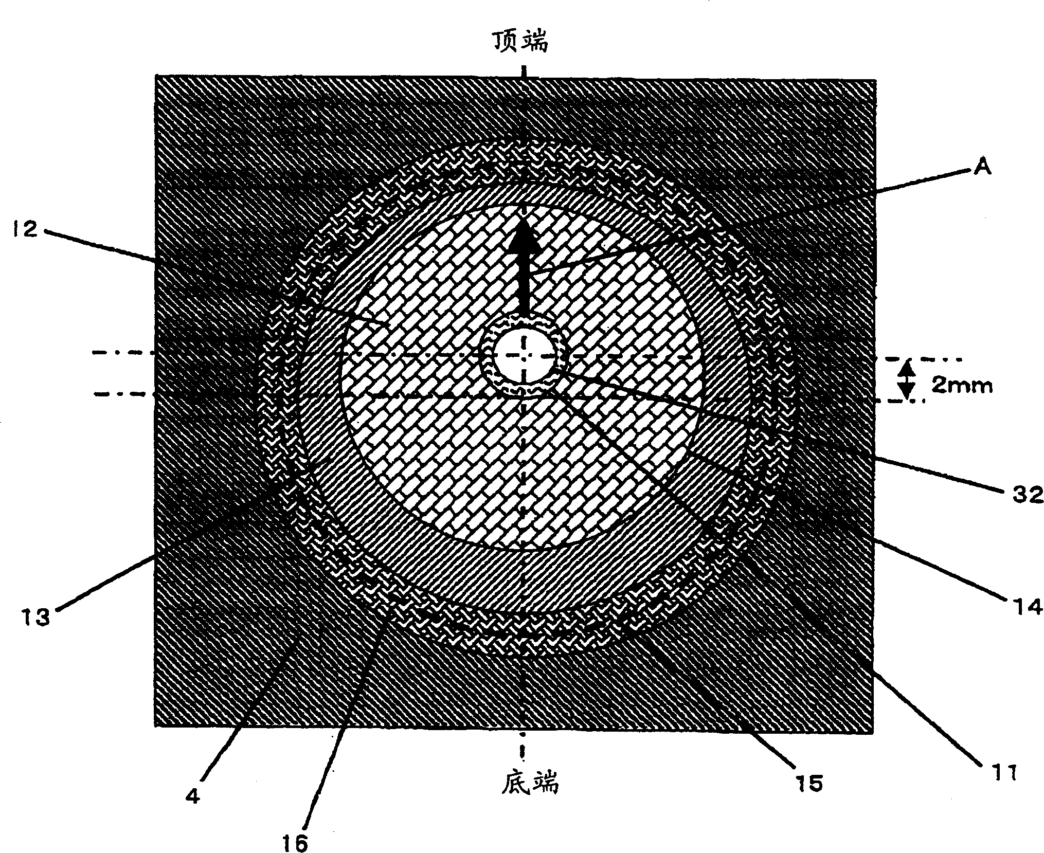
[0038] [die]
[0039] The die 1 includes a fixed...
PUM
 Abstract
Description
Claims
Application Information