

Humidifier with rotation sprayer
A technology of rotating nozzles and rotating heads, applied in ultrasonic humidifiers, air humidification systems, heating methods, etc., can solve the problems of uniform distribution of unfavorable moisture, and achieve the effect of simple structure, reasonable design and good use effect.
Inactive Publication Date: 2006-11-29
王昊然
View PDF0 Cites 13 Cited by
- Summary
- Abstract
- Description
- Claims
- Application Information
AI Technical Summary
Problems solved by technology
[0002] Now ordinary humidifiers have fixed nozzles, and the sprayed water mist faces a fixed direction, which is not conducive to the uniform distribution of moisture.
Method used
View moreImage
Smart ImageViewing Examples

Examples
Embodiment
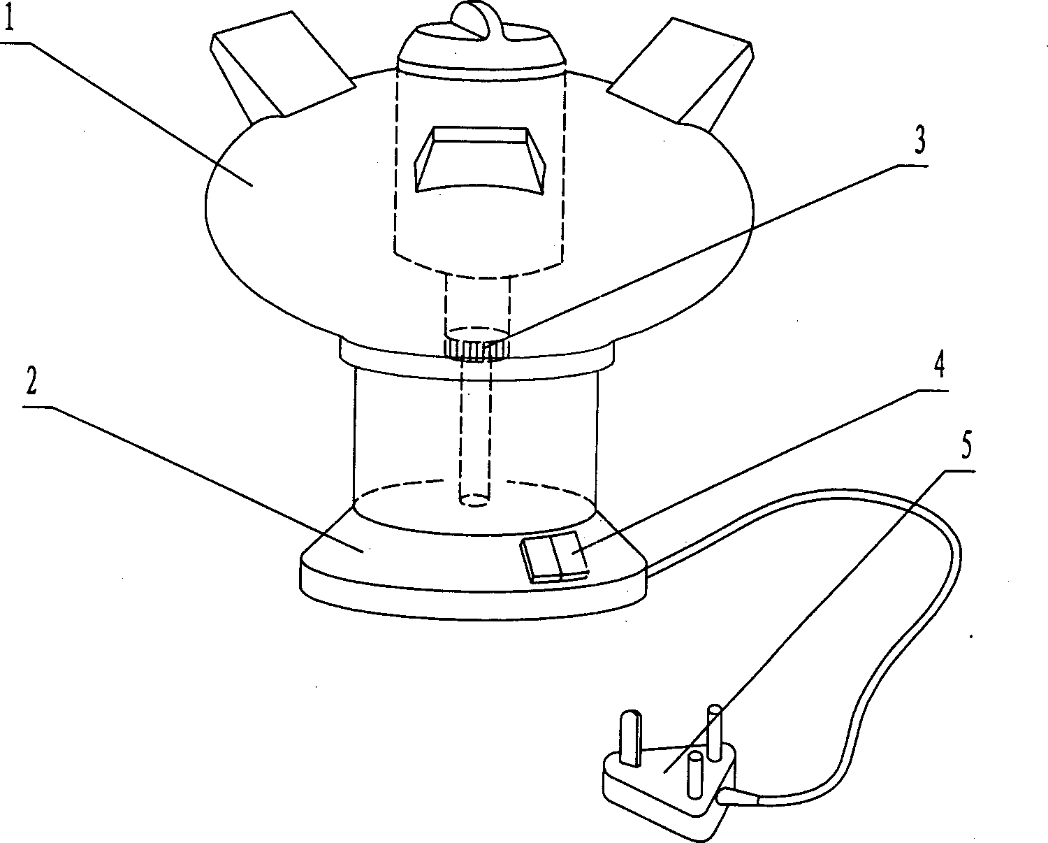
[0010] Embodiment: The structure is shown in the accompanying drawings. It consists of a rotating head 1, a base 2, an atomizer 3, a key switch 4, and a power plug 5. A driving motor is connected to the rotating head 1 through a central shaft, the ultrasonic nebulizer 3 is fixed in the middle of the base, and the working power is connected by a power cord and a plug. When in use, turn on the power, add an appropriate amount of pure water, press the button switch 4, the ultrasonic atomizer 3 will work, and the rotating head 1 will start to rotate. Under the action of centrifugal force, the mist will be sprayed from the rotating nozzle to the surroundings. It has the advantages of simple structure, good use effect and novel shape.
Login to View More PUM
 Abstract
The invention relates to an adding wet implement with rotation sprayer. It belongs to the manufacture technology field of domestic electric implements. It is made up of rotation sprayer, base, ultrasonic sprayer and power pin. The down side of the rotation nozzle is jointed with the up side of the base through the ring runner. The center of the base sets driven motor. The driven motor is jointed with the pin through the power line. The center of the driven motor is jointed with the rotation sprayer. The sprayer is fixed at the middle of the base. When using, get the power, give befitting pure water, turn of the button switch, and than the ultrasonic sprayer runs, the rotation sprayer begin to rotate. Under the effect of the centrifugal strength, the mirage sprays around from the rotation sprayer. It has the advantages of reasonable design, simple frame and good usage effect.
Description
technical field [0001] The invention relates to a humidifier with a rotatable spray head, which belongs to the technical field of household appliance manufacturing. Background technique [0002] Now ordinary humidifiers have fixed nozzles, and the sprayed water mist faces a fixed direction, which is not conducive to the uniform distribution of moisture. Contents of the invention [0003] Aiming at the deficiencies of the prior art, the invention provides a humidifier with reasonable design, simple structure, convenient use, and a rotatable nozzle with enlarged mist spreading area. [0004] The purpose of the present invention is achieved through the following technical solutions: a humidifier with a rotatable spray head, consisting of a rotatable head, a base, an atomizer and a power plug, the lower part of the rotatable head is connected to the upper opening of the base through an annular chute, and the base There is a driving motor in the center, the driving motor is co...
Claims
Login to View More Application Information
Patent Timeline
 Patent Type & AuthorityApplications(China)
IPC IPC(8): F24F6/14F24F6/16
CPCY02B30/80Y02B30/70
Inventor王昊然许福运
Owner王昊然