Method for implementing legal monitoring

A technology of lawful interception and interception system, applied in the field of interception, can solve the problems of restricting the application of lawful interception business and reducing the service quality of lawful interception business, and achieve the effect of expanding the scope of application and improving the quality of business service.

Inactive Publication Date: 2006-11-29
HUAWEI TECH CO LTD
View PDF0 Cites 10 Cited by
  • Summary
  • Abstract
  • Description
  • Claims
  • Application Information

AI Technical Summary

Problems solved by technology

[0010] from above figure 1 As can be seen from the flow shown, in the prior art, when the monitoring system issues a monitoring instruction to the HLR in the CS and needs to set a target user as a monitoring object, if the HLR determines that the target user is in an active state, that is, the target user When a call is being connected or a session is in progress, the interception instruction issued by the interception system will not be accepted, and the media gateway controller of the target user's visited network where the target user is currently located in the CS and the media gateway of the target user's visited network are not connected. A bearer connection will be established with the interception system. In this way, the interception system cannot obtain the content of the current session of the target user or the content of the upcoming session that is currently being continued. Therefore, the application of legal interception services in CS is greatly limited. Reduced business service quality of lawful interception business

Method used


Image

  • Method for implementing legal monitoring
  • Method for implementing legal monitoring
  • Method for implementing legal monitoring

Examples


Embodiment 1

[0053] In this embodiment, the specific implementation process of the present invention is described by taking the monitoring system as an example to initiate a bearer establishment call to the media gateway controller of the network visited by the target user.

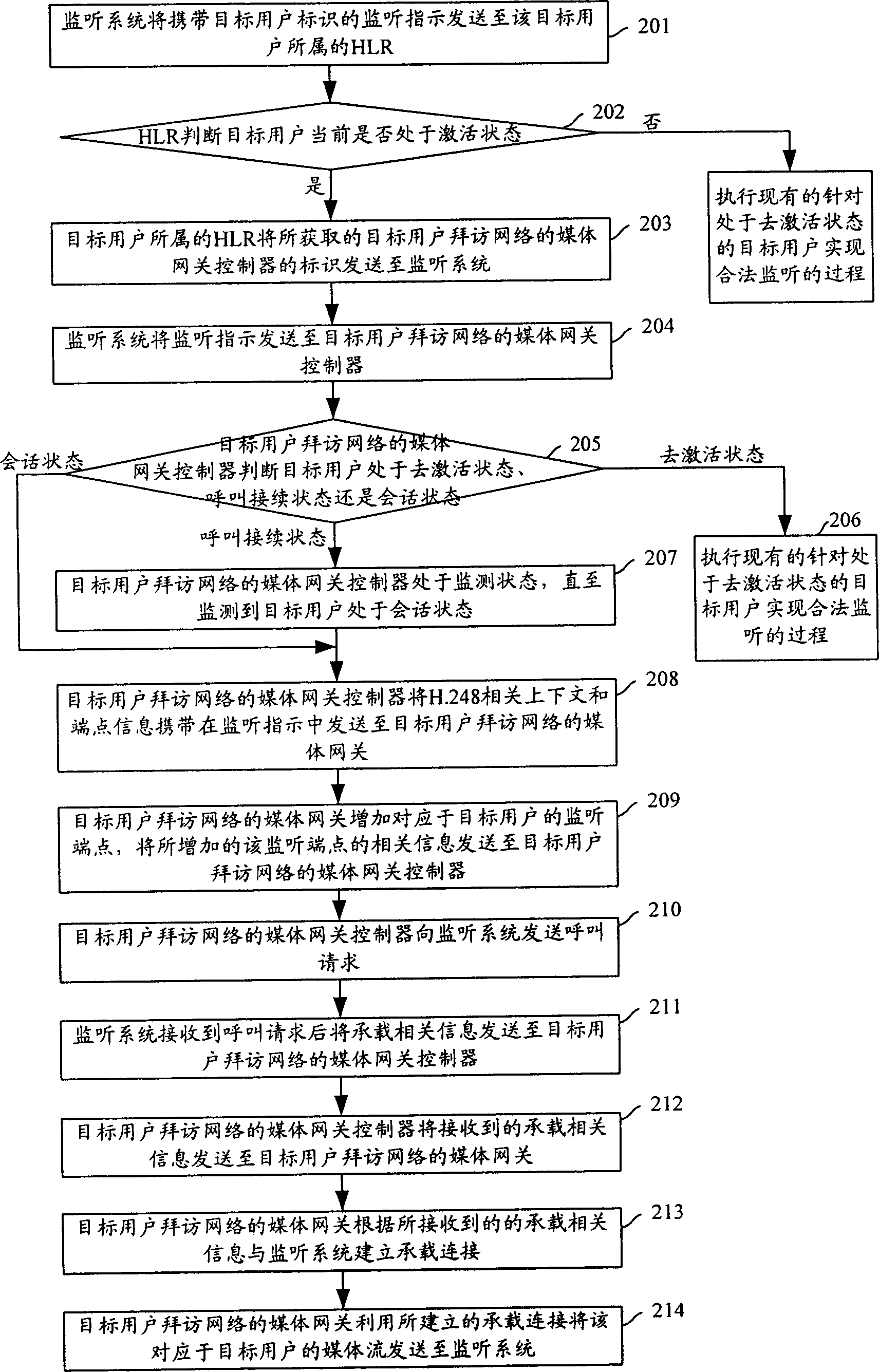
[0054] figure 2 It is a flow chart of implementing lawful interception in the CS in Embodiment 1 of the present invention. see figure 2 , in the present invention, the process of realizing lawful interception in CS specifically includes the following steps:

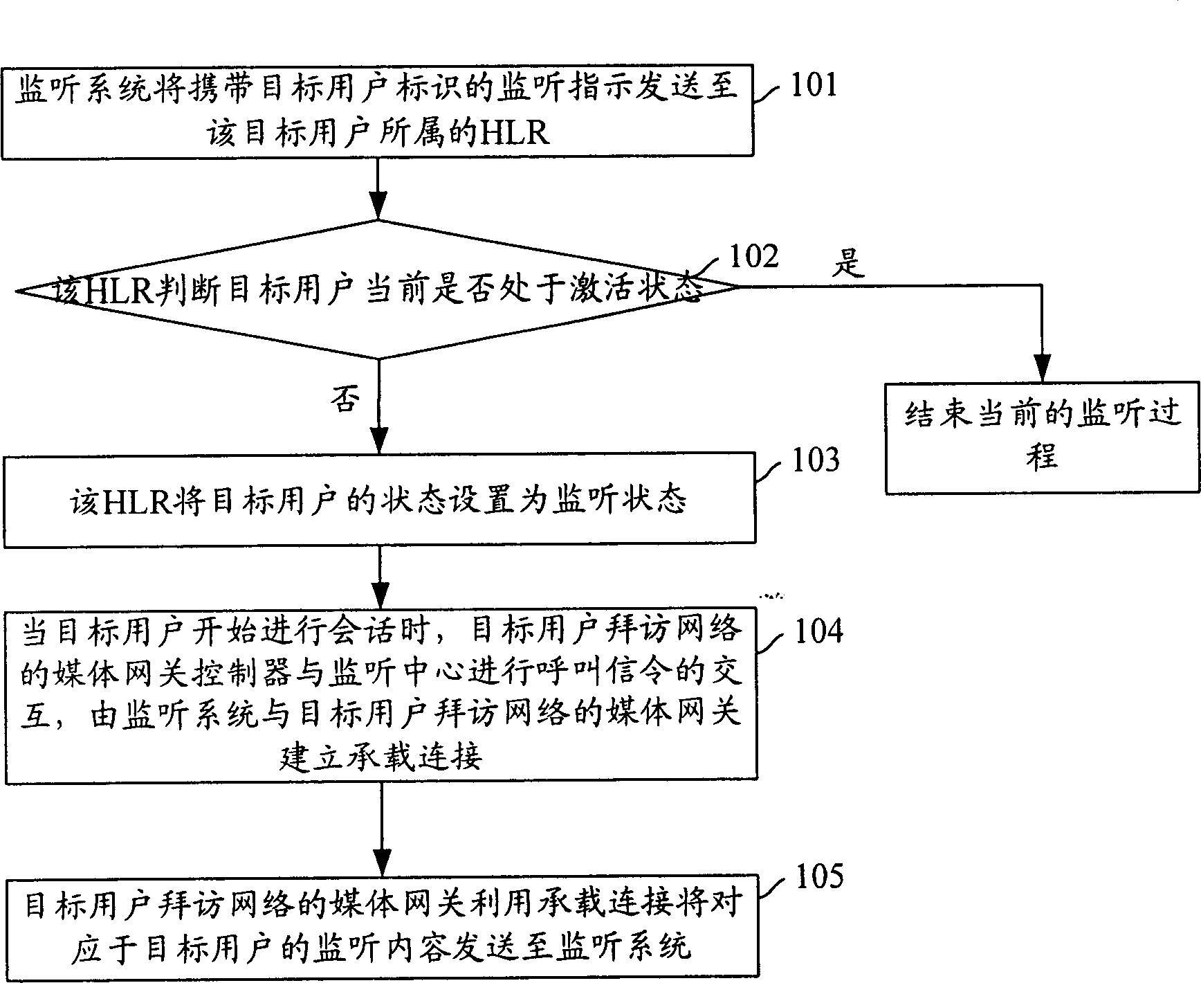
[0055] Step 201: the monitoring system sends a monitoring instruction to the HLR to which the target user belongs.

[0056] Here, the interception instruction sent by the interception system to the HLR to which the target user belongs carries the identity of the target user, interception content information and other relevant interception information. Here, the identifier of the target user may include: MSISDN, IMSI, IMEI, SIP URI, TEL URL, NAI. The monitor...

Embodiment 2

[0090] In this embodiment, the specific implementation process of the present invention is described by taking the media gateway controller of the network visited by the target user to initiate a call to the monitoring system to establish a bearer connection as an example.

[0091] Figure 4 It is a flow chart of implementing lawful interception in the CS in Embodiment 2 of the present invention. see Figure 4 , in the present invention, the process of realizing lawful interception in CS specifically includes the following steps:

[0092] All descriptions of steps 401 to 407 are the same as those of steps 201 to 207.

[0093] Step 408: The MGC of the network visited by the target user sends an interception response to the interception system.

[0094]Here, when sending the monitoring response, the media gateway controller of the network visited by the target user may further carry the information that the target user is in a session state in the monitoring response and send...


PUM


Abstract

This invention discloses a method for realizing legal monitor including: after a HLR belonging to a target user receives a monitor instruction with a target user ID sent by a monitor system, it judges if the target user is at the activating state at the present based on the target user ID carried in the monitor instruction, if so, it triggers the monitor system and the media gateway of the target user access network to set up bearing connection, the media gateway uses the set-up bearing connection to send the media flow corresponding to the target user to the monitor system.

Description

technical field [0001] The invention relates to interception technology, in particular to a method for realizing legal interception of active users in circuit domain (CS). Background technique [0002] Lawful interception refers to law enforcement agencies (LEA) that are approved by the corresponding authorized agencies to monitor public communication network communication services in accordance with relevant national laws and public communication network industry norms. [0003] figure 1 It is a flow chart of implementing lawful interception in CS in the prior art. Referring to FIG. 1, when it is necessary to monitor the calling process of a target user in the CS, the process of implementing monitoring in the prior art specifically includes the following steps: [0004] Step 101: the interception system sends an interception instruction carrying a target user identifier to a home location register (HLR) to which the target user belongs. [0005] Step 102: After receiving...

Claims


Application Information

Patent Timeline
Patent Type & Authority Applications(China)
IPC IPC(8): H04M3/22
Inventor 梅武钢
Owner HUAWEI TECH CO LTD
Why Eureka
Try Eureka