Feeding structure of die and die employing same

一种模具、进浇的技术,应用在塑胶模具进浇结构及应用该进浇结构的模具领域,能够解决限制塑胶流量、影响生产效率、收缩不均等问题

Inactive Publication Date: 2006-12-27
HONG FU JIN PRECISION IND (SHENZHEN) CO LTD +1
View PDF0 Cites 3 Cited by
  • Summary
  • Abstract
  • Description
  • Claims
  • Application Information

AI Technical Summary

Problems solved by technology

In order to avoid defects caused by uneven shrinkage, the diameter of the columnar gate area 20 must be consistent with the thickness of the mold cavity 30, so the diameter of the columnar gate area is limited, which in turn limits the flow of plastic into the cavity and affects production efficiency; especially when manufacturing This effect is especially significant when the thickness of the part is thin

Method used


Image

  • Feeding structure of die and die employing same
  • Feeding structure of die and die employing same
  • Feeding structure of die and die employing same

Examples


Embodiment Construction

[0019] The pouring structure of the mold of the present invention takes injection molding as an example.

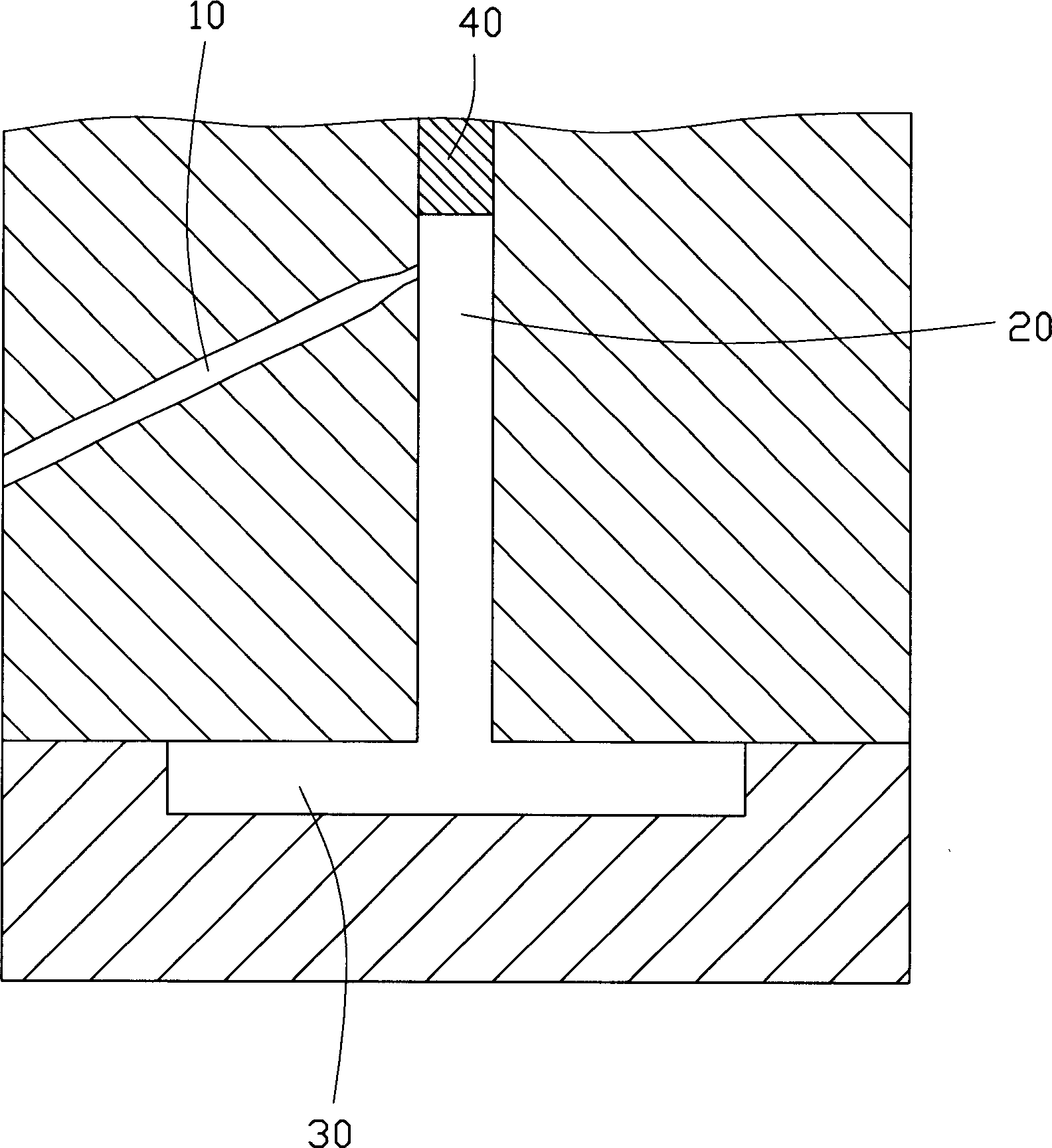
[0020] For the preferred implementation mode of the mold pouring structure of the present invention, please refer to Figure 2 to Figure 4 , the mold includes an upper mold 1 and a lower mold 2, and a parting surface 12 is formed between the upper mold 1 and the lower mold 2.

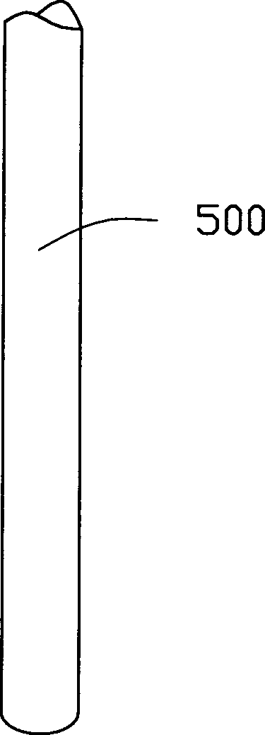
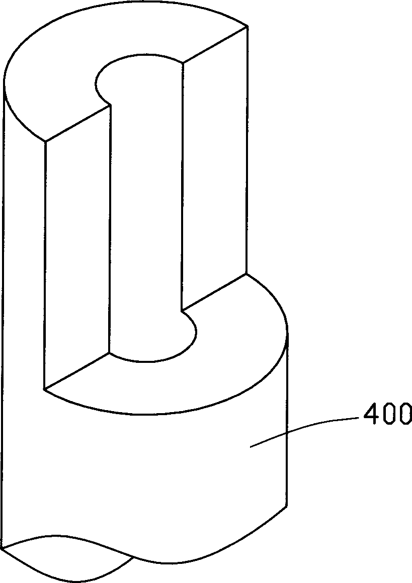
[0021] The upper mold 1 is provided with a pouring structure, and the lower mold 2 is provided with a cavity 300, and the cavity 300 is used to form molten plastic into a product. The gate structure includes a latent gate area 100 , a columnar gate area 200 , a thimble sleeve 400 and a thimble 500 .

[0022] The latent gate area 100 is connected to the columnar gate area 200 at a certain angle. After injection molding, the plastic in the latent gate area 100 can form a waste, and the waste can pass through the formed shear during demoulding or parting. Force, the gate waste is automatically cut o...


PUM


Abstract

The invention discloses a die casting gate structure and die using this structure. The die casting gate structure includes: thimble, thimble sleeve, first gate area and second gate area. The first gate area communicates with the second gate area in certain angle. The thimble passes through the thimble sleeve, one part of which is hold and fixed inside the thimble sleeve, and the rest is hold in the second gate area. With the die casting gate structure and die using this structure of the invention, flux of moulding injection can be increased, and surface property of the product is improved.

Description

【Technical field】 [0001] The invention relates to a pouring structure for a mold, in particular to a pouring structure for a plastic mold and a mold using the pouring structure. 【Background technique】 [0002] In products such as electronics, automobiles, motors, electrical appliances, instruments, meters, home appliances and communications, 60% to 80% of parts must be formed by molds, so mold processing has become an important technology in industrial production. [0003] In the injection molding process, the plastic raw material needs to flow into the mold cavity through the flow channel. If the molten plastic raw material is directly injected into the mold cavity, the melt flow will be affected by the cavity resistance and the cavity wall, which will cause defects in the part. To reduce defects, it is necessary to adopt different pouring methods according to the shape and structure of the workpiece. The pouring structure mainly refers to the structure connecting the flow...

Claims


Application Information

Patent Timeline
Patent Type & Authority Applications(China)
IPC IPC(8): B29C45/27
CPCB29C2045/2714B29C45/2708B29C45/2806B29C45/40
Inventor 彭镜齐李恒纬
Owner HONG FU JIN PRECISION IND (SHENZHEN) CO LTD
Why Eureka
Try Eureka