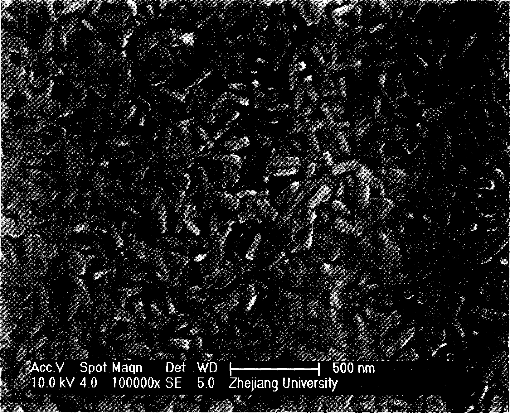
Process of depositiong TiN film on glass substrate
A glass substrate and thin film technology, applied in the field of depositing TiN thin films, can solve the problems of cumbersome operation process and achieve the effect of simple process
- Summary
- Abstract
- Description
- Claims
- Application Information
AI Technical Summary
Problems solved by technology
Method used
Image
Examples
Embodiment 1
[0016] 1) Clean the glass substrate with 10% hydrofluoric acid;
[0017] 2) Put the glass substrate on the graphite support of the reaction chamber of the chemical vapor deposition device, and the reaction chamber is evacuated to -0.02Mpa, and N 2 Clean the reaction chamber;
[0018] 3) Adjust the distance between the nozzle and the glass substrate to be 5cm;
[0019] 4) Heating the reaction chamber to 600°C;
[0020] 5) TiCl 4 , NH 3 and N 2 The reaction gas is passed into the reaction chamber, where TiCl 4 The flow rate is 300sccm, NH 3 The flow rate is 150sccm, N 2 The flow rate is 900sccm, the pressure of the reaction chamber is -0.02MPa, the deposition is carried out at a temperature of 600°C, and the reaction time is 90s. After the reaction is completed, stop feeding the gas and cool it down.
[0021] The resistivity of the prepared TiN film is 1.5×10 4 μΩ.cm, the reflectivity in the infrared region is 45%, and with the increase of wavelength, the reflectivity o...
Embodiment 2
[0023] 1) Clean the glass substrate with 10% hydrofluoric acid;
[0024] 2) Put the glass substrate on the graphite support of the reaction chamber of the chemical vapor deposition device, and the reaction chamber is evacuated to -0.02Mpa, and N 2 Clean the reaction chamber;
[0025] 3) Adjust the distance between the nozzle and the glass substrate to be 25cm;
[0026] 4) Heating the reaction chamber to 600°C;
[0027] 5) TiCl 4 , NH 3 and N 2 The reaction gas is passed into the reaction chamber, where TiCl 4 The flow rate is 300sccm, NH 3 The flow rate is 150sccm, N 2 The flow rate is 900sccm, the pressure of the reaction chamber is -0.02MPa, the deposition is carried out at a temperature of 600°C, and the reaction time is 90s. After the reaction is completed, stop feeding the gas and cool it down.
[0028] The prepared TiN thin film is non-conductive and has a reflectivity of 35% in the infrared region, and the emissivity of the thin film tends to decrease as the wav...
Embodiment 3
[0030] 1) Clean the glass substrate with 10% hydrofluoric acid;
[0031] 2) Put the glass substrate on the graphite support of the reaction chamber of the chemical vapor deposition device, and the reaction chamber is evacuated to -0.02Mpa, and N 2 Clean the reaction chamber;
[0032] 3) Adjust the distance between the nozzle and the glass substrate to be 13cm;
[0033] 4) Heating the reaction chamber to 600°C;
[0034] 5) TiCl 4 , NH 3 and N 2 The reaction gas is passed into the reaction chamber, where TiCl 4 The flow rate is 300sccm, NH 3 The flow rate is 150sccm, N 2 The flow rate is 900sccm, the pressure of the reaction chamber is -0.02MPa, the deposition is carried out at a temperature of 600°C, and the reaction time is 90s. After the reaction is completed, stop feeding the gas and cool it down.
[0035] The resistivity of the prepared TiN film is 7.5×10 3 μΩ.cm, the reflectivity in the infrared region can reach more than 50%, and it shows an upward trend with the...
PUM
| Property | Measurement | Unit |
|---|---|---|
| electrical resistivity | aaaaa | aaaaa |
| electrical resistivity | aaaaa | aaaaa |
| reflectance | aaaaa | aaaaa |
Abstract
Description
Claims
Application Information
 - R&D
- Intellectual Property
- Life Sciences
- Materials
- Tech Scout
- Unparalleled Data Quality
- Higher Quality Content
- 60% Fewer Hallucinations
Browse by: Latest US Patents, China's latest patents, Technical Efficacy Thesaurus, Application Domain, Technology Topic, Popular Technical Reports.
© 2025 PatSnap. All rights reserved.Legal|Privacy policy|Modern Slavery Act Transparency Statement|Sitemap|About US| Contact US: help@patsnap.com

