
Apparatus for producing parallel light pipe and method thereof

A technology of collimator and equipment, applied in the coupling of optical waveguides, metal processing equipment, optics, etc., can solve the problems of reduced productivity, reduced productivity of collimator 10, reduced production efficiency, etc.

Inactive Publication Date: 2003-08-27
SAMSUNG ELECTRONICS CO LTD
View PDF0 Cites 1 Cited by
  • Summary
  • Abstract
  • Description
  • Claims
  • Application Information

AI Technical Summary

Problems solved by technology

[0010] However, the traditional collimator is manufactured by hand, so the production efficiency is significantly reduced, and the reliability of the product is also reduced accordingly
Also, it takes a long time to produce collimators, reducing productivity
As a result, the productivity of the collimator 10 is significantly reduced

Method used


Image

  • Apparatus for producing parallel light pipe and method thereof
  • Apparatus for producing parallel light pipe and method thereof
  • Apparatus for producing parallel light pipe and method thereof

Examples


Embodiment Construction

[0030] The present invention will now be described in detail with preferred embodiments of the invention illustrated in the accompanying drawings, wherein like reference numerals refer to like elements throughout. The embodiments will be described below in order to explain the present invention by referring to the figures.

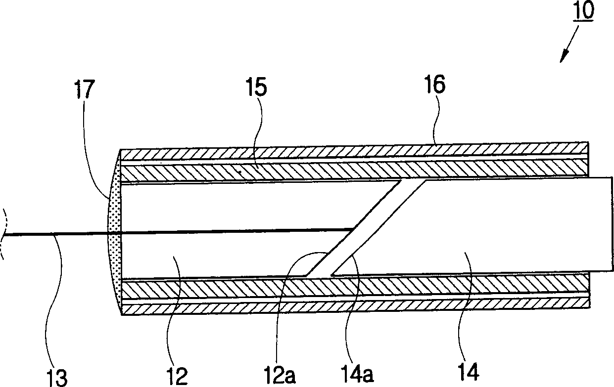
[0031] Embodiments of the present invention will be described in detail below with reference to the accompanying drawings. Because the present invention includes the above described figure 1 elements, so any descriptions are related to figure 1 Combine. and figure 1 Any elements and components that are the same will be assigned the same reference numerals.

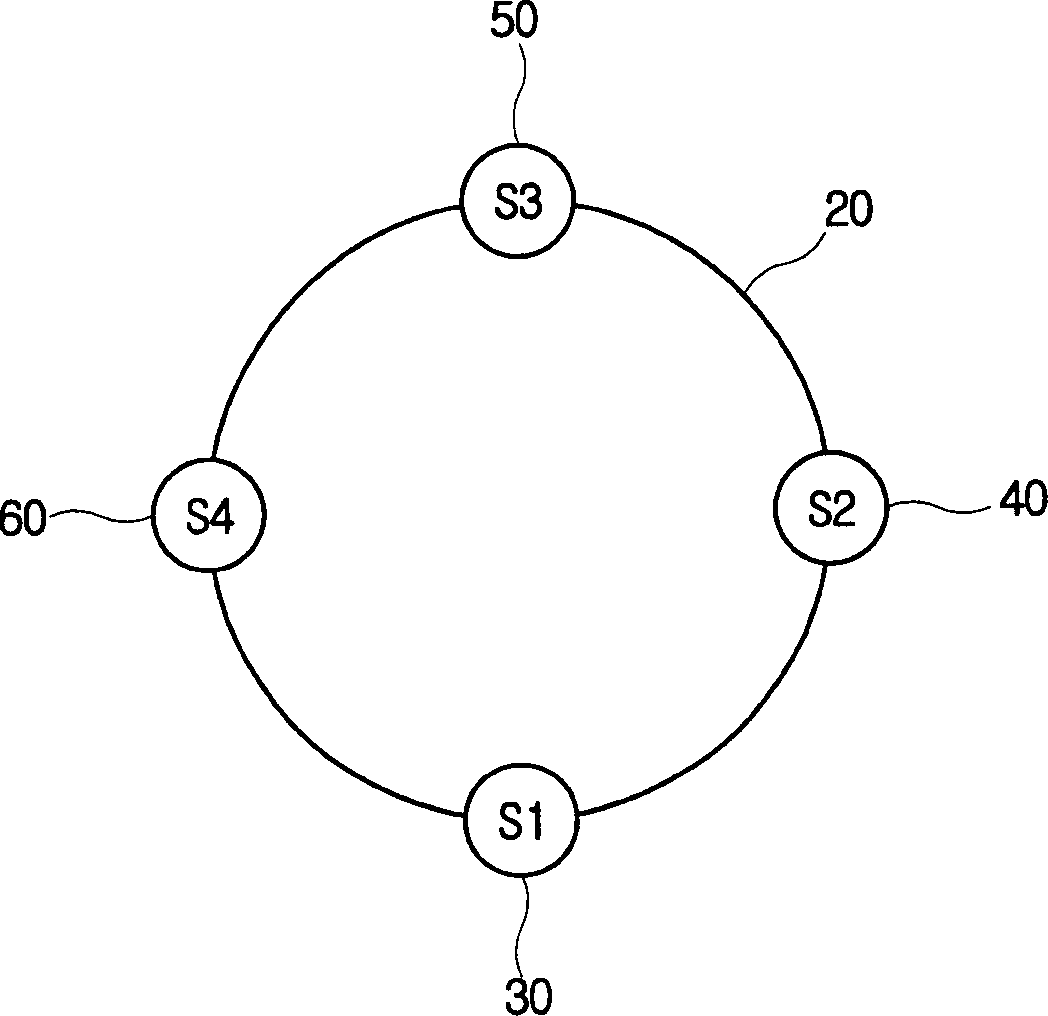
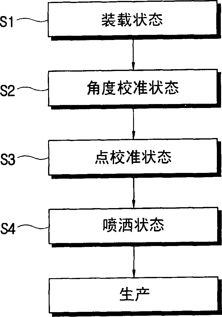
[0032] Such as figure 2 and 3 As shown, an apparatus for automatically manufacturing collimators includes a turntable 20 having the shape of a rotating disk. The equipment includes a loading part 30 distributed along the circumference of the turntable 20, an angle alignment part 40, a point ali...


PUM


Abstract

An automatic collimator manufacturing apparatus includes a loading part being loaded a glass tube, into which a GRIN lens is fixedly inserted, and a pigtail formed with at least one fiber, an angle aligning part allowing the pigtail to be inserted into the glass tube and coaxially aligning the pigtail with the GRIN lens, a spot aligning part controlling an optical property between the pigtail and the GRIN lens, and a dispensing part fixedly attaching the pigtail to the glass tube. With this automatic collimator manufacturing apparatus, a product reliability increases, a production time period is shortened, and a productivity of a collimator is enhanced.

Description

technical field [0001] The present invention relates to a kind of equipment and method for manufacturing collimator, more particularly, relate to a kind of lens (pigtail) with tail fiber and glass tube with gradient index lens automatically assembled into collimator Apparatus and methods. Background technique [0002] The so-called collimator refers to an optical communication device that converts light received from a light source into a beam of parallel rays. Collimators are generally used as components in various devices such as optical communication devices, semiconductor devices, and the like. [0003] General collimator 10, such as figure 1 As shown, it includes a lens (pigtail) 12 and a GRIN (gradient index) lens that are co-located on a coaxial line, a glass tube that accommodates and supports a lens (pigtail) 12 and a GRIN lens 14 with a fiber tail 15, and a metal sleeve 16 formed on the outside of the glass tube 15 for protecting the glass tube 15. [0004] At ...

Claims


Application Information

Patent Timeline
Patent Type & Authority Applications(China)
IPC IPC(8): G02B6/32B23Q3/00B23Q15/00G02B6/10G02B6/26G02B27/30
CPCY10T29/49895Y10T29/49998Y10T29/53091Y10T29/4978Y10T29/53961Y10T29/49764G02B6/32Y10T29/49778Y10T29/53974Y10T29/53978Y10T29/53374Y10T29/53039G02B27/30
Inventor 黄冕淳朴台焕宣烘锡林京元金炳坤
Owner SAMSUNG ELECTRONICS CO LTD
Learn More