Unlock instant, AI-driven research and patent intelligence for your innovation.

Encoder device

An encoder, photodiode technology

Inactive Publication Date: 2007-01-10
MITSUMI ELECTRIC CO LTD
View PDF1 Cites 6 Cited by
  • Summary
  • Abstract
  • Description
  • Claims
  • Application Information

AI Technical Summary

Problems solved by technology

[0012] Therefore, in particular, if the X-direction length 2×X1 of the light-transmitting portion 11a and the light-shielding portion 11b is made as small as the manufacturing limit, there is a problem that the resolution of the encoder device cannot be further improved.

Method used


Image

  • Encoder device
  • Encoder device
  • Encoder device

Examples


Embodiment Construction

[0033] Embodiments of the present invention will be described below with reference to the drawings.

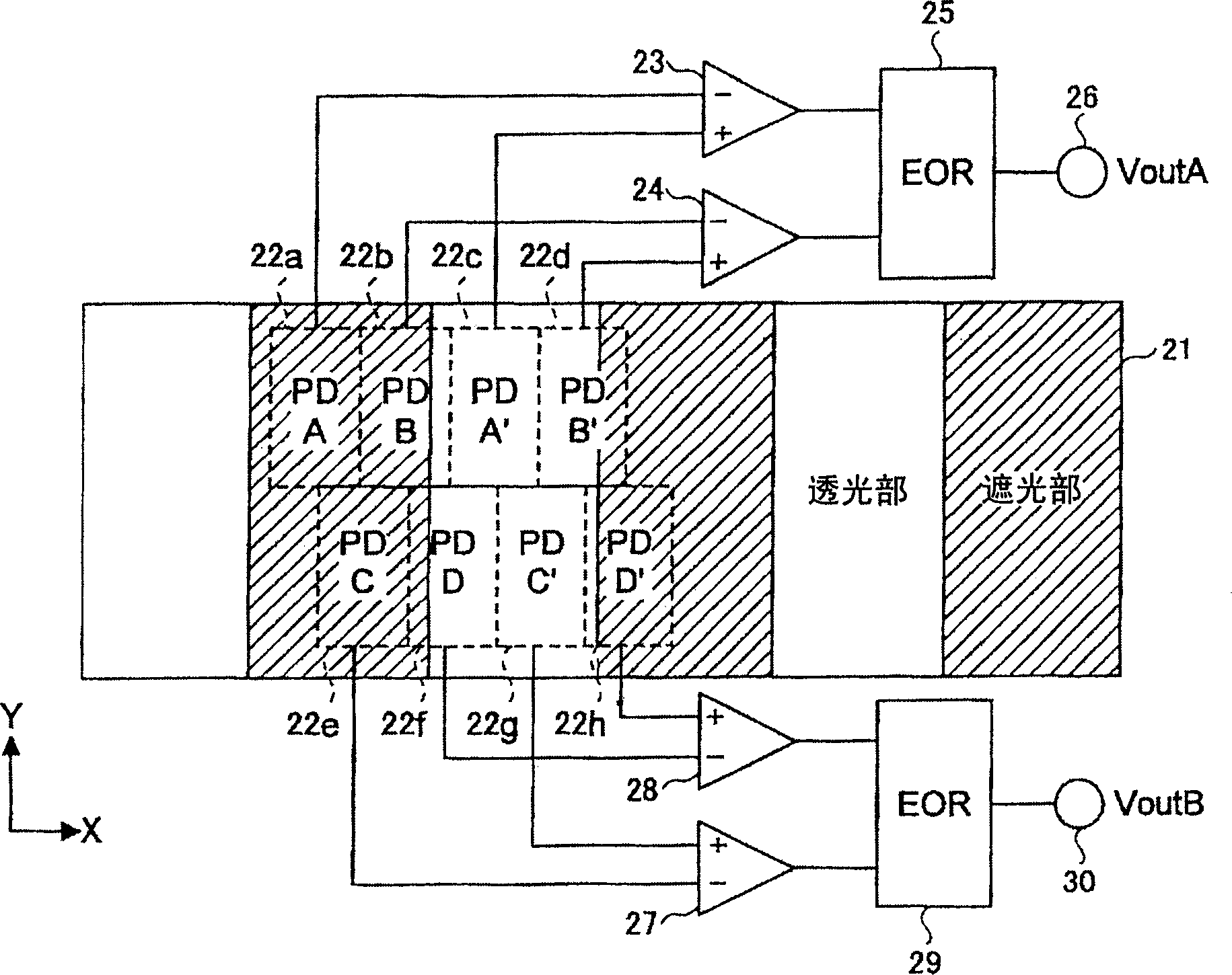
[0034] figure 1 It is a plan configuration diagram of one embodiment of the encoder device of the present invention. In the same figure, the encoder device is composed of a light source, a slit member 21 and an integrated circuit 22 which are not shown.

[0035] The light source and the integrated circuit 22 are fixed in a separated and opposed state. The slit member 21 is free to move in the X direction (rightward or leftward) relative to the light source and the integrated circuit 22 in a state inserted between the light source and the integrated circuit 22 . The slit member 21 is fixed to the object to be measured, and moves in the X direction due to linear motion or rotational motion of the object to be measured. The composition and Figure 7 The conventional encoder device shown in (B) is the same.

[0036] Such as figure 2 As shown in the top view of the integrate...


PUM


Abstract

It is an object of the present invention to provide an encoder device capable of increasing the resolution. It has: the first to fourth photodiodes adjacent to the X direction with a length of X1 in the X direction; relative to the first to fourth photodiodes in the X direction, only 1 / 2 in the X direction. The 5th to the 8th photodiodes that are adjacent in the Y direction that is perpendicular to the direction and adjacent in the X direction are the 5th to 8th photodiodes with a length of X1 in the X direction; the light-transmitting part and the light-shielding part with a length of 2×X1 in the X direction are repeatedly set and placed in the X direction. the slit member moving in the direction; A logic circuit for generating a second detection signal whose phase is shifted by 1 / 4 cycle of the first detection signal with respect to the first detection signal from the output signals of the fifth to eighth photodiodes.

Description

technical field [0001] The present invention relates to an encoder device, and more particularly to an encoder device that detects motion of an object to be measured and generates pulses according to the motion. Background technique [0002] Encoder devices that generate pulses according to the movement of the object to be measured are conventionally used as devices for detecting motion such as linear motion or rotational motion of the object to be measured and inputting it into digital equipment such as a computer. [0003] Figure 7 (A) and (B) show a plan view and a side view of an example of a conventional encoder device. In the same figure, the encoder device is composed of a light source 10 , a slit member 11 and an integrated circuit 12 . [0004] The light source 10 and the integrated circuit 12 are fixed in a separated state facing each other. The slit member 11 is free to move in the X direction (rightward or leftward) relative to the light source 10 and the inte...

Claims


Application Information

Patent Timeline
Patent Type & Authority Applications(China)
IPC IPC(8): G01D5/36
CPCG01D5/36G01D5/34746G01D2205/90
Inventor 三野宫秀亮胁直纯田中润一郎
Owner MITSUMI ELECTRIC CO LTD