Method of manufacturing head suspension

一种制造方法、磁头的技术,应用在记录头的配置/安装、支持头、臂部件的结构等方向,能够解决冲击特性下降等问题

Active Publication Date: 2007-01-10
NHK SPRING CO LTD
View PDF2 Cites 1 Cited by
  • Summary
  • Abstract
  • Description
  • Claims
  • Application Information

AI Technical Summary

Problems solved by technology

Furthermore, when the B1 frequency is low, the impact characteristics also decrease

Method used


Image

  • Method of manufacturing head suspension
  • Method of manufacturing head suspension
  • Method of manufacturing head suspension

Examples


no. 1 example

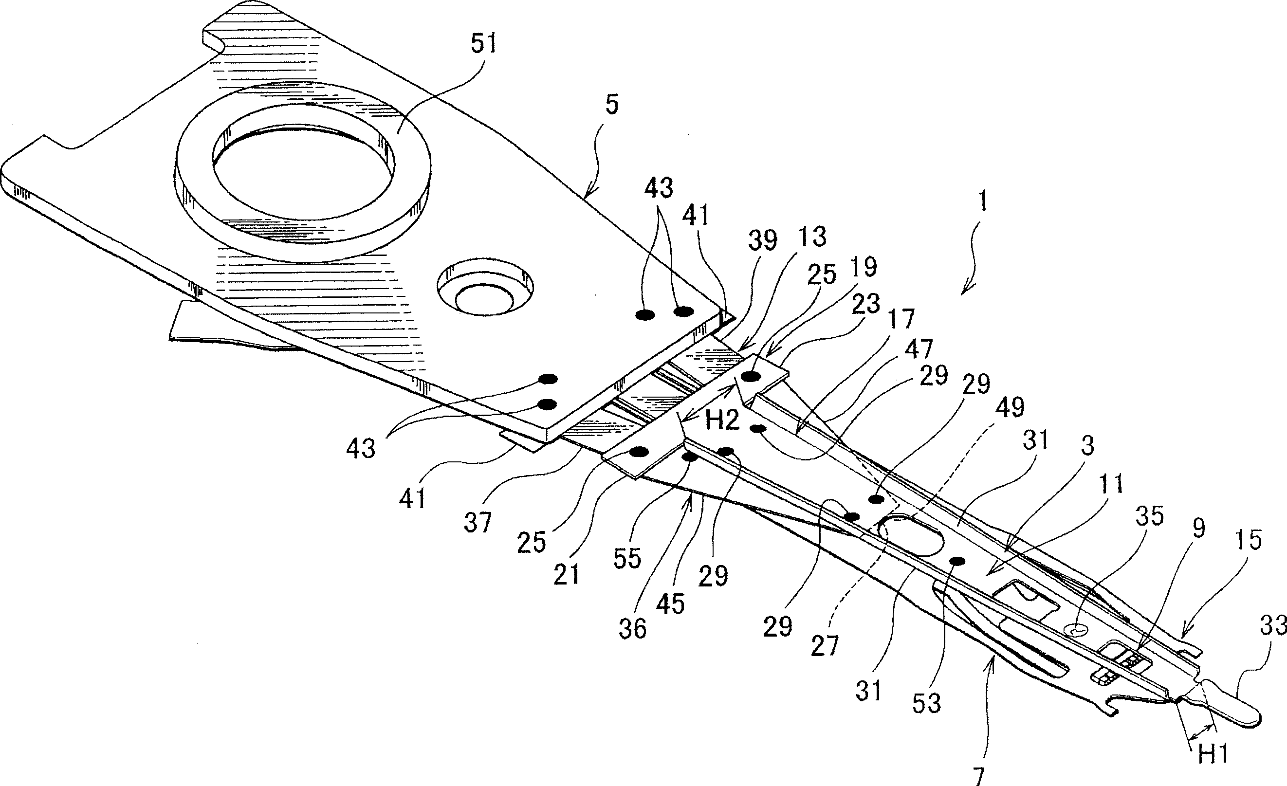
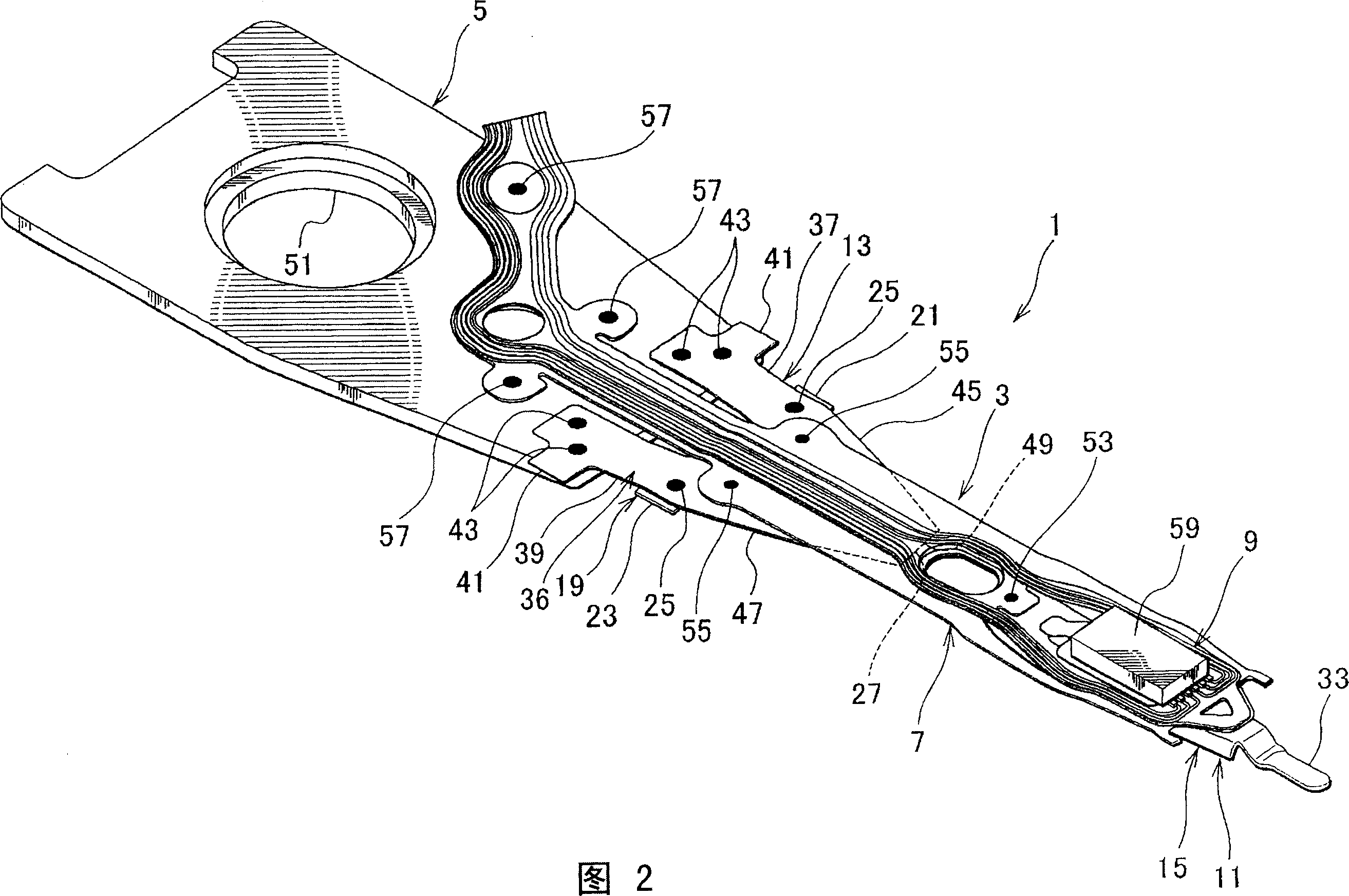
[0072] The following will refer to figure 1 and 2 to illustrate the structure of the head suspension.

[0073] figure 1 is a perspective view showing the head suspension according to the first embodiment of the present invention on the side facing away from the disk, and FIG. 2 shows figure 1 Perspective view of the middle head suspension on the disk side. In this specification, a "disk" is a storage medium mounted in a hard disk drive to which data is written and from which data is read by a magnetic head supported by a head suspension. The side facing away from the magnetic disk is the side where the direction of the head suspension 1 faces away from the magnetic disk. On the other hand, the disk side is the other side of the head suspension 1 facing the disk.

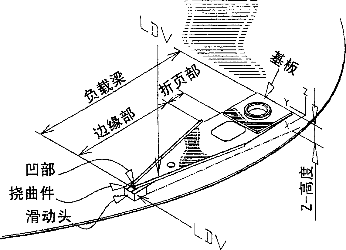
[0074] The shock characteristic of the load beam is represented by the magnitude of the shock by which the slider of the load beam is lifted from the disk surface. The phenomenon that the slider of the load b...

example 1

[0142] The B1 frequencies of Example 1 and Comparative Example 1 are not much different from each other, they are 5.99 kHz and 6.08 kHz because both have high longitudinal stiffness and are light in weight. However, Comparative Example 2 was thick and heavy, so its B1 frequency dropped to 5.61 kHz.

[0143] The T1 frequencies of Example 1 and Comparative Example 1 are not much different from each other, they are 9.09 kHz and 9.18 kHz because both have high longitudinal stiffness and are light in weight. However, Comparative Example 2 is thick and has a large inertia, so its T1 frequency drops to 7.76 kHz.

[0144] The rocking frequencies of Example 1 and Comparative Example 2 are not much different from each other, they are 14.54 kHz and 14.89 kHz because both have high stiffness in the rocking direction. On the other hand, Comparative Example 1 has low stiffness in the shaking direction, so its shaking frequency is reduced to 12.27 kHz.

[0145] The STA of Example 1 and Com...

no. 2 example

[0174] will refer to Figure 44 A second embodiment of the present invention will be described. Figure 44 is a plan view corresponding to manufacturing steps for realizing the method of manufacturing the head suspension according to the second embodiment. The manufacturing steps of the second embodiment are basically the same as those of the first embodiment, and therefore, the same or corresponding parts are denoted by the same reference numerals in FIG. 35 .

[0175] In the manufacturing method of the second embodiment, the lamination and bonding steps E1 and F1 are employed instead of the lamination and bonding steps E and F of the first embodiment. exist Figure 44 Among them, step (5) corresponds to lamination step E1, and step (6) corresponds to welding step F1.

[0176] In the lamination step E1 shown in step (5), the rigid member chain 71 , the elastic member chain 73 , each substrate, and each flexure 7 are laminated and arranged in an appropriate relationship. T...


PUM

PropertyMeasurementUnit
lengthaaaaaaaaaa
lengthaaaaaaaaaa
resonance frequencyaaaaaaaaaa

Abstract

A method for manufacturing a magnetic head suspension, which can smoothly form the magnetic head suspension, and the T1 wind resistance of the formed magnetic head suspension is improved by increasing the T1 frequency and the shaking frequency, and the impact characteristics are improved. The method comprises: a rigid member chain manufacturing step forming a rigid member chain product, wherein the rigid member is continuously provided; a flexure manufacturing step forming a flexure integrally formed with the elastic member and the reinforcing member; The base manufacturing step, which forms the base; the lamination and joining step, which laminates and joins the rigid part chain, the elastic part chain, the base and the flexure to form a stack; the cutting step, which cuts from the stack and detach each head suspension.

Description

technical field [0001] The present invention relates to a method of manufacturing a head suspension for a hard disk drive integrated into an information or data processing device, such as a computer. Background technique [0002] E.g, Figure 49 Indicates an existing head suspension. Figure 49 is a plan view showing a conventional head suspension 101 integrated into a hard disk drive. The head suspension 101 includes a base 103 , a load beam 105 and a flexure 107 . The load beam 105 includes a rigid member 109 and a resilient member 111 . The rail 113 is formed along the side edge in the longitudinal direction of the rigid part 109 by raising the side edge from the rigid part 109 . [0003] Figure 50 It is a partial sectional view partially showing an example of a hard disk drive in which the head suspension 101 is mounted. like Figure 50 As shown, the hard drive has a bracket 115 including arms 117 . Each head suspension 101 is connected to the arm 117 of the brack...

Claims


Application Information

Patent Timeline
Patent Type & Authority Applications(China)
IPC IPC(8): G11B21/21
CPCG11B5/4833Y10T29/49025Y10T29/49027Y10T29/4903Y10T29/49032
Inventor 多田一半谷正夫泷川健一绵谷荣二
Owner NHK SPRING CO LTD
Why Eureka
Try Eureka