A display panel

A display panel and pixel element technology, applied in static indicators, nonlinear optics, instruments, etc., can solve problems such as grating patterns, and achieve the effect of improving image quality

Inactive Publication Date: 2007-01-10
KONINKLIJKE PHILIPS ELECTRONICS NV
View PDF3 Cites 0 Cited by
  • Summary
  • Abstract
  • Description
  • Claims
  • Application Information

AI Technical Summary

Problems solved by technology

[0003] The problem with said known display device is that a grating pattern can appear, especially when only th

Method used


Image

  • A display panel
  • A display panel
  • A display panel

Examples


Embodiment Construction

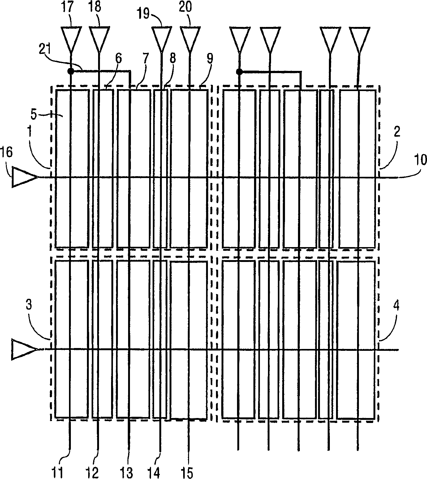
[0025] figure 1 A part of a first embodiment of the display panel of the present invention is shown in . The display panel includes a matrix of pixels 1-4 arranged in rows and columns. figure 1 and 2 Indicates only a portion of the display panel. Display panels more representative of the invention typically include more pixels, for example 832x624, 1024x768, 1280x960 or 1600x1200 pixels in commonly used standard resolutions. figure 1 is a plan view of the side of the display panel from which light is emitted in use. Each pixel 1-4 occupies a certain area from which light is emitted, ie available for forming an image. As indicated with respect to the first pixel 1 , the first pixel 1 comprises a plurality of sub-pixel elements 5-9, each occupying a contiguous sub-pixel element area constituting the partial area of ​​the first pixel 1 for forming an image.

[0026] The types of display technologies that can be used for the display panels described herein are described in mo...


PUM


Abstract

A display panel comprises a plurality of pixels (1-4;22;57). Each of the pixels (1-4;22;57) comprises a plurality of sub-pixel elements (5-9;31-46;48-56) occupying respective continuous sub-pixel element areas within a pixel area. At least two non-adjacent sub-pixel elements (5,7;45,46;52,53) are coupled to receive substantially a same driving signal. The coupling may be realized via a conductor (21) or by coupling the at least two non-adjacent sub-pixel elements (5,7;45,46;52,53) to respective driver circuits receiving substantially a same input signal.

Description

technical field [0001] The invention relates to a display panel comprising a plurality of pixels. The invention also relates to a display device. Background technique [0002] US 5,208,689 discloses a display device with an electro-optic medium between two support plates, wherein a pixel divided into a plurality of sub-pixels is defined on at least one support plate by means of a pixel electrode. A subpixel has a certain surface area, which is at most equal to the surface area of ​​other subpixels, and the surface area is adjustable under multiple transmission levels, while other subpixels can only be switched between two extreme transmission states. In one embodiment, the row and column electrodes are divided into sub-electrodes with a width ratio of 4:2:1:1. A cell is defined at the intersection region of the electrodes, and by appropriately driving the sub-electrodes, the cell can completely or partially change its electro-optic properties. Since the electrodes are div...

Claims


Application Information

Patent Timeline
IPC IPC(8): G09G3/20G02F1/1335G09G3/34
CPCG09G2300/0443G09G2300/0452G09G3/3433G09G2320/0233G09G3/2074G02F2201/52G09G2320/0276G02F1/133
Inventor R·范迪克
Owner KONINKLIJKE PHILIPS ELECTRONICS NV
Why Eureka
Try Eureka