Lever and floating steam trap of balanced and two-valve seat

A double-seat, float-type technology, applied in steam traps, mechanical equipment, etc., can solve the problems of poor stability and reliability, and achieve the effects of pressure balance, good stability and reliability, and long service life

Active Publication Date: 2007-01-17
洪有福
View PDF1 Cites 5 Cited by
  • Summary
  • Abstract
  • Description
  • Claims
  • Application Information

AI Technical Summary

Problems solved by technology

[0004] The purpose of the present invention is to provide a double-seat cut-off lever with good pressure balance, stability and reliability, aiming at the disadvantages of poor stability and reliability of the existing double-seat cut-off lever float type steam trap. Ball Float Steam Traps

Method used


Image

  • Lever and floating steam trap of balanced and two-valve seat
  • Lever and floating steam trap of balanced and two-valve seat
  • Lever and floating steam trap of balanced and two-valve seat

Examples


Embodiment Construction

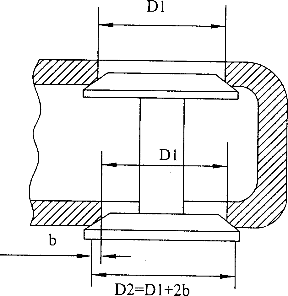
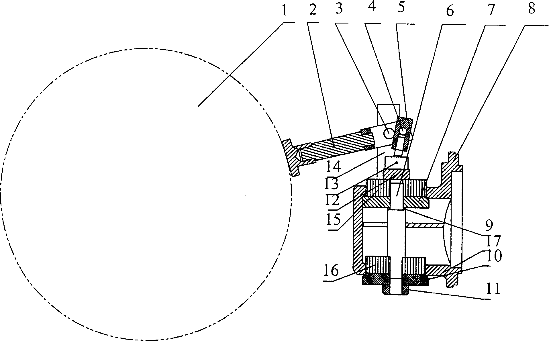
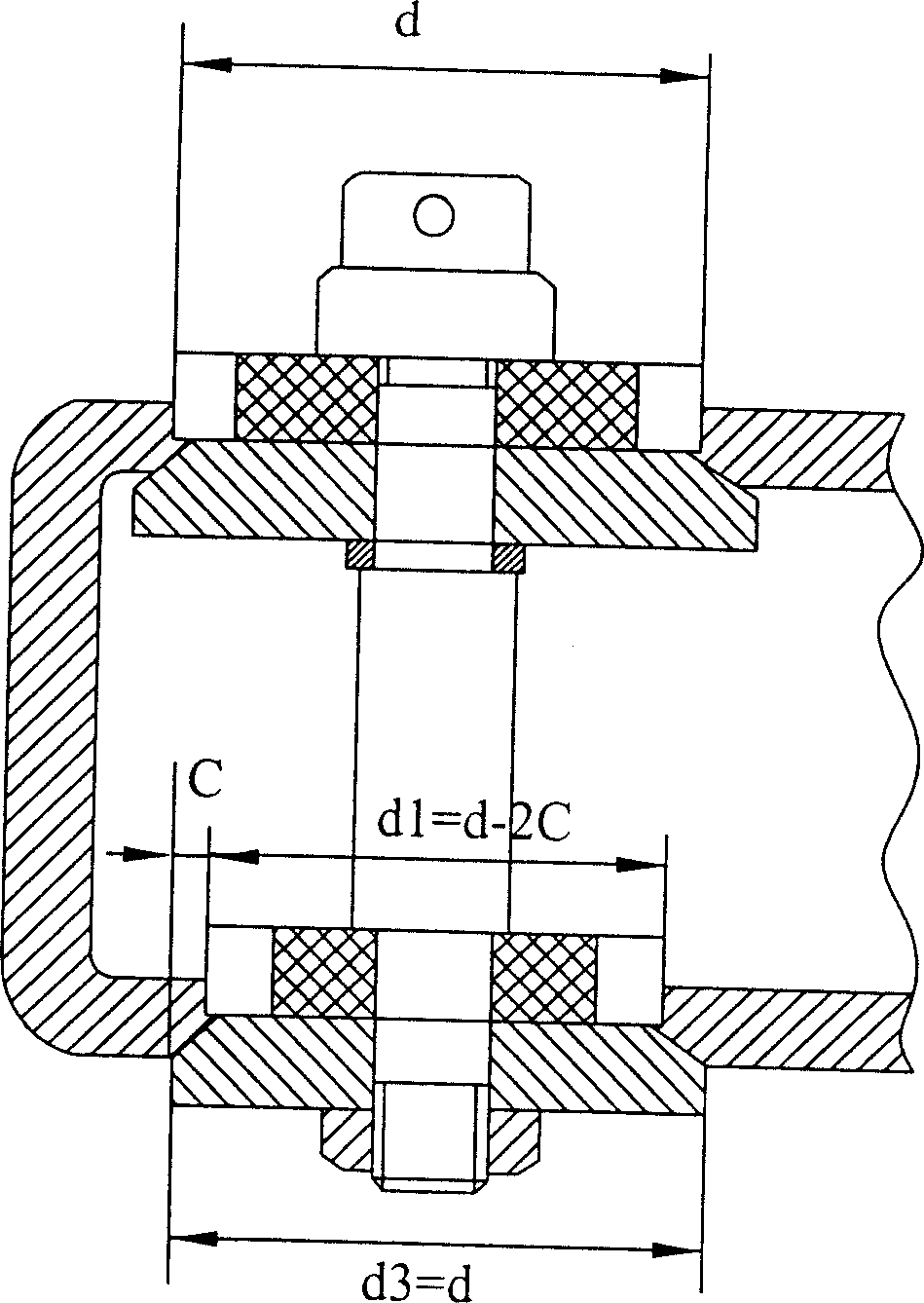
[0012] Such as figure 2 , shown in 3, is provided with float 1, lever 2, pin shaft 3, pin 4, connecting rod 5, valve stem 6, upper valve core 7, upper valve core positioning block 15, upper valve seat 8, gasket 9, Lower spool 10, lower spool positioning block 16, lower valve seat 17, nut 11, coupling head 12, coupling pin 13 and lever support 14. One end of the lever 2 is connected with the floating ball 1, the other end of the lever 2 is connected with the upper end of the connecting rod 5 with the pin 4, the lever 2 is matched with the pin shaft 3 and supported on the lever bracket 14, and the lever bracket 14 is set on the upper valve seat Above 18, the lower end of the connecting rod 5 is matched with the connecting head 12 through the connecting pin 13, the gasket 9, the upper valve core 7 and the upper valve core positioning block 15 are inserted into the upper part of the valve stem 6, and the upper valve core 7 is set on the upper valve seat 8 and matched with the lo...


PUM


Abstract

This invention relates to a kind of bivalve seat stop type level float steam trap. It includes float ball, level, pin shaft, pin, connecting bar, valve stem, upper and lower spools, upper and lower spool locating blocks, upper and lower valve seats, shim, nut, connecting head, connecting pin and level support. One end of level connects to float ball, the other end connects to the upper end of pin and connecting bar. Level and pin shaft are connected and are supported on the level support. The level support is arranged above the upper level seat. The lower end of connecting rod is connected to connecting head through connecting pin. The shim, upper spool and upper spool-locating block are all capped on the upside of valve stem. The upper spool is in the upper valve seat and connects to the nut and lower conical surface of the upper valve seat. The connecting head connects to the top of valve stem. The adjustable underside of valve stem inserts into lower spool and lower spool locating block. The lower spool is in the lower valve seat and connects to the lower conical surface of the lower valve seat.

Description

technical field [0001] The invention relates to a steam trap, in particular to a double valve seat cut-off lever float type steam trap. Background technique [0002] The existing steam traps are mechanical, thermostatic and thermodynamic. The usual cut-off lever float type steam trap adopts conical surface sealing, and generally has two structures of single valve seat and double valve seat. The cut-off lever float type steam trap with a single valve seat structure has a relatively simple structure, but it is under pressure in one direction when it is working. When it is opened, its pressure area is large, so the opening resistance is large, and it is only suitable for small displacement and valves. Traps with low steam pressure. If the double valve seat structure is adopted, since there are two discharge holes, the flow area of ​​the discharge holes can be increased, thus greatly increasing the drainage of the trap, and when it is in the closed state, the upper and lower v...

Claims


Application Information

Patent Timeline
IPC IPC(8): F16T1/24
Inventor 陈午生洪有福
Owner 洪有福
Why Eureka
Try Eureka