Arc-control device for circuit breaker

A technology of arc extinguishing device and circuit breaker, which is applied in the direction of circuit breaker components, etc., which can solve the problems of wall damage, only one gas outlet, unfavorable metal free gas escape quickly, etc., and achieve the effect of prolonging the service life

Active Publication Date: 2005-04-27
CHANGSHU SWITCHGEAR MFG CO LTD (FORMER CHANGSHU SWITCHGEAR PLANT)
View PDF0 Cites 12 Cited by
  • Summary
  • Abstract
  • Description
  • Claims
  • Application Information

AI Technical Summary

Problems solved by technology

In order to ensure that there is sufficient pressure in the arc extinguishing chamber 2 to achieve the purpose of quickly extinguishing the arc, it is generally considered that the gas outlet can only be unique and cannot have two
However, the applicant found that the arc extinguishing device with the above structure has the following defects: when an arc occurs, an arc is generated in the arc extinguishing chamber 2 due to the separation of the upper and lower contacts 3, 5, and the generation of this arc makes the arc extinguishing chamber 2 The temperature in the arc extinguishing chamber rises sharply, and a large amount of gas is generated in the arc extinguishing chamber 2, including the metal free gas released from the upper and lower contacts 3 and 5, and the metal gas produced after the arc extinguishing grid 4 is corroded by the arc. The free gas and the wall of the arc extinguishing chamber 2, that is, the gas produced by the inner wall of the shell 1 (technically called the wall) made of gas-generating materials, under the condition of limited volume of the arc extinguishing chamber 2, the arc extinguishing Due to the accumulation of a large amount of gas in the chamber 2, the pressure in the arc extinguishing chamber 2 increases sharply to form high-pressure gas. The high-pressure gas often has no time to quickly escape from the second opening 8, often causing the wall of the arc extinguishing chamber 2 to be damaged by huge pressure and pressure. Damaged by high temperature; in addition, metal free gas is mainly generated when the upper and lower contacts 3, 5 are repelled, and is close to the third opening 9, and forms a metal free gas accumulation area there, but as the gas outlet The distance between the second opening 8 and the metal free gas accumulation area is relatively long, so that the metal free gas cannot quickly escape from the second opening 8 to the arc extinguishing chamber 2. Once cooled, the metal free gas will accumulate in the extinguishing chamber. On the wall of the arc chamber 2, when accumulated to a certain extent, it will cause the re-ignition of the arc, which is quite unfavorable for the rapid arc extinguishing of the arc extinguishing device
It may be considered that as long as the second opening 8 is displaced as a whole, that is, the above-mentioned phenomenon can be eliminated by approaching the third opening 9, however, further tests by the applicant have shown that this approach will bring about the problem of losing sight of the other, because the second opening If 8 moves downward, then when the upper and lower contacts 3 and 5 are repelled, the generated gas tends to run upwards, which is not conducive to the rapid escape of the gas from the arc extinguishing chamber 2, and the overall opening of the second opening 8 is relatively small. Large, if it is moved down, it will be difficult to maintain the gas pressure in the arc extinguishing chamber 2, unable to achieve rapid arc extinguishing, and it will also bring about the rapid escape of metal free gas that is not conducive to the metal free gas accumulation area, which will further aggravate the extinction The wall of the arc chamber 2 is damaged by the huge pressure and high temperature

Method used


Image

  • Arc-control device for circuit breaker
  • Arc-control device for circuit breaker
  • Arc-control device for circuit breaker

Examples


Embodiment Construction

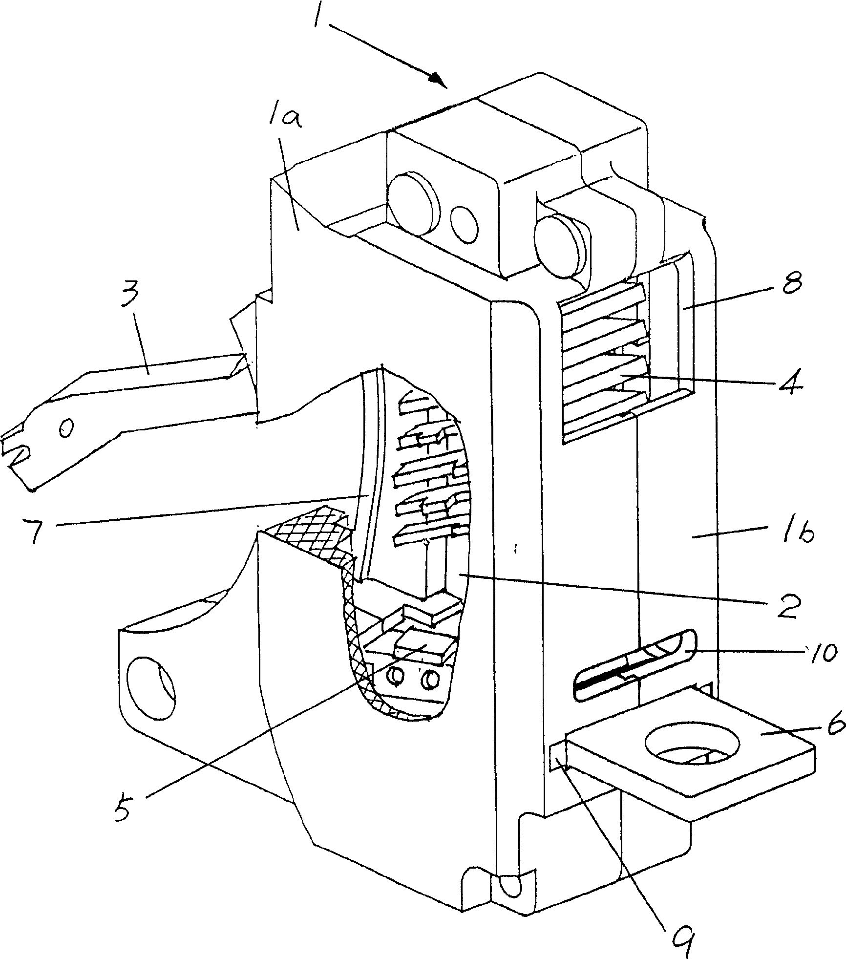
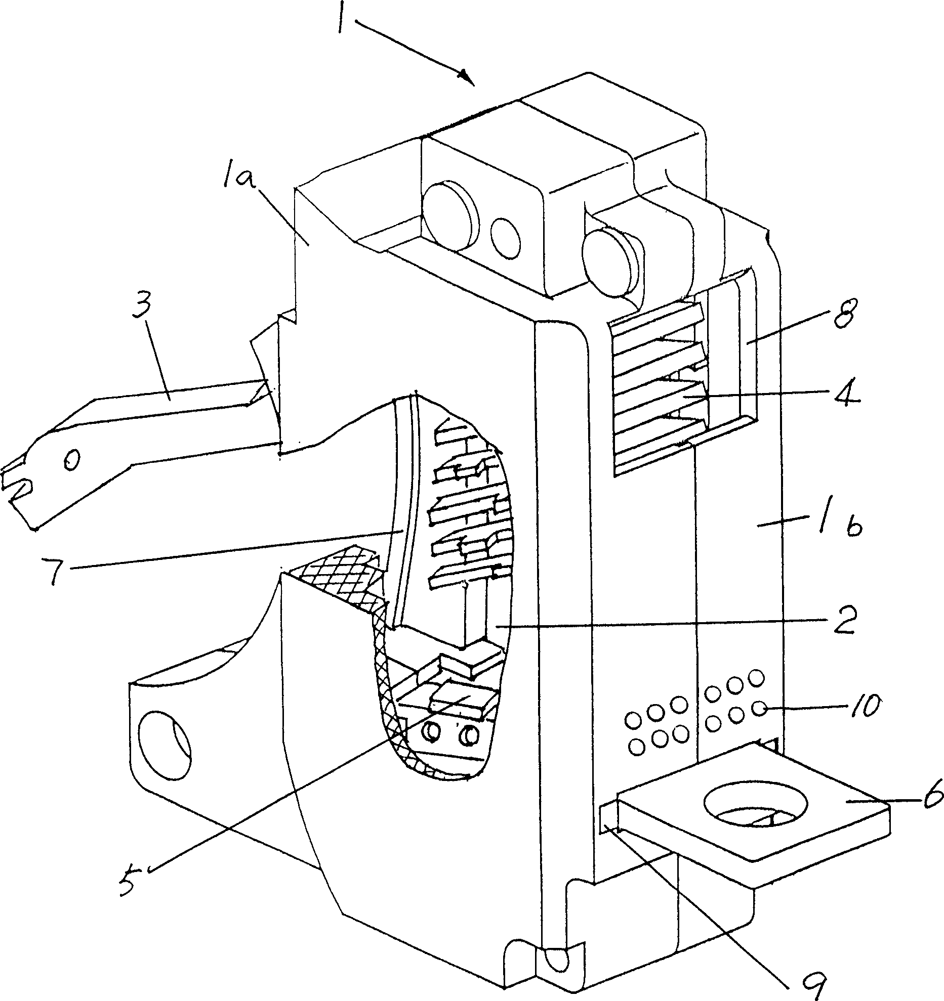
[0015] Such as figure 2 As shown, on the back of the housing 1 and between the second and third openings 8 and 9, a fourth opening 10 is added, which is mainly used to quickly escape the metal free gas. The fourth opening 10 is as close as possible to the metal free gas. The accumulation area, that is, the contact area where the arc root is located. Since the arc root is the part where a large amount of contact metal free gas is generated and enters the arc channel, the ionization effect is strong and the concentration of conductive ions is high. Therefore, the air flow acting on the arc root is important for the arc to increase the arc column resistance and improve the breaking performance. effect. However, the solution of the present invention can quickly discharge metal free gas and adjust the gas flow direction at the arc root through the fourth opening 10, and the fourth opening 10 is set as a long and thin opening to avoid the pressure drop in the arc extinguishing cha...


PUM


Abstract

The present invention is arc extinguisher for breaker and belongs to the field of electric equipment technology. The arc extinguisher consists of casing with four openings, upper and lower contacts and arc extinguishing sheets. The present invention has the advantages of balanced pressure inside the arc extinguishing chamber, fast escape and no accumulation of free metal gas produced during arc distinction, less damage of walls of the arc extinguishing chamber, and long service life of the arc extinguisher.

Description

technical field [0001] The invention relates to an arc extinguishing device of a circuit breaker, in particular to an arc extinguishing device of a plastic shell type circuit breaker, and belongs to the technical field of electric appliances. Background technique [0002] Existing circuit breakers generally include arc extinguishing devices, tripping devices, contact systems, and operating mechanisms. The arc extinguishing device is a part of the circuit breaker. Its function is to generate an arc when the moving and static contacts of the circuit breaker, that is, the upper and lower contacts are separated. Therefore, the arc will enter the arc extinguishing chamber during the generation process, and the arc will be introduced between the grids through the arc extinguishing grid, and the arc will be cut into short arcs in series, so that the arc will become thinner and the arc voltage drop will be increased rapidly. , so as to achieve the effect of arc extinguishing. [0...

Claims


Application Information

Patent Timeline
Patent Type & Authority Applications(China)
IPC IPC(8): H01H73/18
Inventor 管瑞良王炯华
Owner CHANGSHU SWITCHGEAR MFG CO LTD (FORMER CHANGSHU SWITCHGEAR PLANT)
Why Eureka
Try Eureka