Slurry shielding ordinary-pressure tool changer

A mud-water shield and tool-changing device technology, which is applied to mining devices, mining equipment, earth-moving drilling, etc., can solve the problems of inability to meet the requirements of excavation, inability to meet replacement, and low work efficiency, so as to achieve repeated use and improve construction. Environmental, cost-saving effect

Pending Publication Date: 2019-03-19
ANHUI TONGDU FLOW TECH
View PDF0 Cites 10 Cited by
  • Summary
  • Abstract
  • Description
  • Claims
  • Application Information

AI Technical Summary

Problems solved by technology

With the advancement of the project progress, the tool wear at the front end of the construction shield is serious and cannot meet the requirements of excavation. At this time, it is necessary to manually enter the muddy water pressure chamber with a pressure of 0.8~1.0MPa to work. This kind of environment is harsh a

Method used


Image

  • Slurry shielding ordinary-pressure tool changer

Examples


Embodiment 1

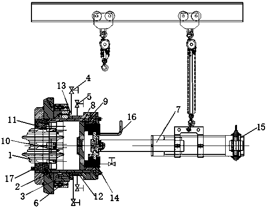
[0023] Embodiment 1: Set a fixed point for the drawing cylinder 7 at the rear end of the cutter head chamber of the slurry shield machine, fix the drawing cylinder 7 through the gourd with the help of a positioning snap ring, connect the hydraulic high-pressure hose, turn on the switch of the hydraulic control unit, and adjust the pulling cylinder 7. Pull the oil cylinder 7 to the F-type pull-push block to cooperate with it, lock the installation lock and remove the bolts on the outer cutter barrel 12 at the same time, keep the additional thrust load of the hydraulic cylinder 7, and further control the retreat of the hydraulic cylinder 7 through the hydraulic control unit switch, and control the retraction amount to The double-opening gate device 3 can be closed to start the double-opening gate device 3. The double-opening gate hydraulic cylinder 6 ensures the rapid closing of the double-opening gate device 3. At the same time, the flushing high-pressure valve 4 and the pressure...

Embodiment 2

[0024] Embodiment 2: The prepared new cutter cylinder and cutter are hoisted by the sling, and the front-end special-shaped lug of the drawing cylinder 7 is used to rotate and cooperate with the F-shaped pull and push block at the end of the cutter cylinder to push and pull the inner cutter cylinder of the hob. 2. Before pushing the outer cutter cylinder 12, apply grease on its outer surface to further reduce the friction force. At the same time, when the inner cutter cylinder 2 of the hob is pushed into the first sealing ring, start the double-opening gate device again. 7 Double-opening gate hydraulic cylinder 6 Ensure that the double-open gate device 7 is opened quickly, and then gradually apply the upper thrust of the hob inner cutter barrel 2, and then lock the bolt after the knife pushing action is successfully completed.

[0025] To sum up, the muddy water shield normal pressure tool changing device, through the design of the oil injection device 13, can realize the rapid...


PUM


Abstract

The invention discloses a slurry shielding ordinary-pressure tool changer and relates to the technical field of slurry shielding tunneling machines. The slurry shielding ordinary-pressure tool changercomprises a double-hobbing-cutter device, a hobbing cutter inner cutter roller, a double-opening gate device, a flushing high-pressure valve, a pressure-relief high-pressure valve, a double-opening gate hydraulic oil cylinder, a drawing oil cylinder, a cutter roller back cover and a guiding ring, wherein the double-hobbing-cutter device is arranged on a cutter roller mounting base and is arrangedin the hobbing cutter inner cutter roller through a wedge block, and the double-hobbing-cutter device is fixedly connected with the hobbing cutter inner cutter roller through a hexagonal screw. By designing an oil filling device, the slurry shielding ordinary-pressure tool changer can achieve a double-gate sealing face and quickly form oil film, assists sealing, also assists decrease of an opening thrust of a double-opening gate and better assists power consumption reduction of the oil cylinder. In addition, by designing the flushing high-pressure valve and the pressure-relief high-pressure valve on an outer cutter roller, cutter changing safety is achieved, and stuck blockage of the hobbing cutter inner cutter roller is effectively prevented.

Description

technical field [0001] The invention relates to the technical field of muddy water shield tunneling machines, in particular to a device for replacing the cutting and excavating cutter at the front end of the cutter head under normal pressure, in particular to a muddy water shield normal pressure tool changing device. Background technique [0002] In the excavation projects of river-crossing, river-crossing and sea-crossing tunnels with complex terrain and deep buried depth, the mud-water shield construction demonstrates the advantages of the mud-water balance scheme. With the advancement of the project progress, the tool wear at the front end of the construction shield is serious and cannot meet the requirements of excavation. At this time, it is necessary to manually enter the muddy water pressure chamber with a pressure of 0.8~1.0MPa to work. This kind of environment is harsh and the safety factor is low. low efficiency. Second, although there are two mud gate valves conn...

Claims


Application Information

Patent Timeline
IPC IPC(8): E21D9/08E21D9/00E21F17/00E21F17/18
CPCE21D9/08E21D9/00E21F17/00E21F17/18
Inventor 杨凌杰雷鹏王春余宏孝吴劲松陶善祥丁红生
Owner ANHUI TONGDU FLOW TECH
Why Eureka
Try Eureka