Method and system for regulating precision pressure-control well drilling throttle valve

A drilling choke valve and managed pressure drilling technology, which is used in earth-moving drilling, flushing wellbore, and wellbore/well components, etc. and other problems, to achieve the effect of improving the effectiveness and effectively maintaining the balance of the bottom hole pressure.

Active Publication Date: 2015-04-01
BC P INC CHINA NAT PETROLEUM CORP +1
View PDF7 Cites 13 Cited by
  • Summary
  • Abstract
  • Description
  • Claims
  • Application Information

AI Technical Summary

Problems solved by technology

[0003] The key to the normal work of fine MPD is to be able to control the opening of the throttle valve stably and accurately, and to achieve this goal, it is necessary to establish an accurate fine MPD control calculation model, but on the one hand, due to the consideration of multiple parameters , such as back pressure, fluid density, fluid rheology, annular liquid level, hydraulic friction and wellbore geometry, etc., even if the control calculation model is established, its structure is very complicated and it is difficult to achieve precise control; on the other hand , from the perspective of engineering application, the established control model needs to be simplified as much as possible, and it can still maintain good performance under the influence of uncertain factors, and the control algorithm is required to be simple and easy to implement, so as to meet the needs of real-time control, and the actual drilling process is often Non-linear, time-varying and uncertain; therefore, it is difficult to establish an accurate calculation model

Method used


Image

  • Method and system for regulating precision pressure-control well drilling throttle valve
  • Method and system for regulating precision pressure-control well drilling throttle valve
  • Method and system for regulating precision pressure-control well drilling throttle valve

Examples


Example Embodiment

[0016] In order to make the objectives, technical solutions, and advantages of the present invention clearer, the present invention will be further described in detail below in conjunction with the embodiments and the drawings. Here, the exemplary embodiments of the present invention and the description thereof are used to explain the present invention, but not as a limitation to the present invention.

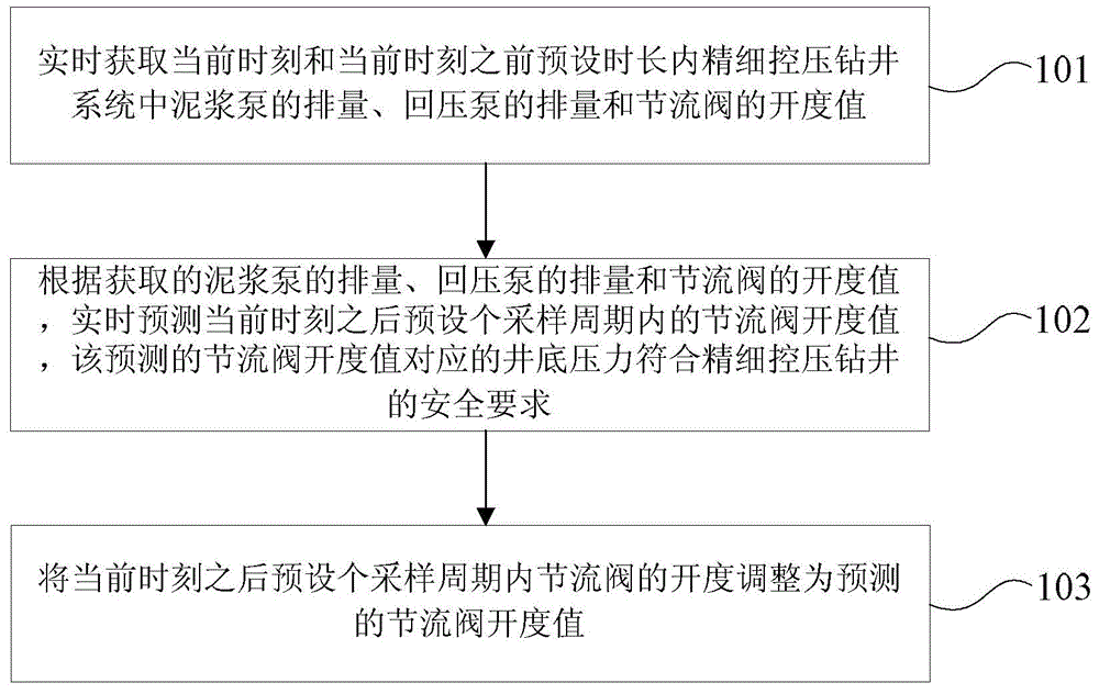
[0017] In the embodiment of the present invention, a method for adjusting the throttle valve of a fine pressure control drilling is provided, such as figure 1 As shown, the method includes:

[0018] Step 101: Obtain in real time the displacement of the mud pump, the displacement of the back pressure pump, and the opening value of the throttle valve in the fine pressure control drilling system within the preset time period before the current time;

[0019] Step 102: According to the acquired displacement of the mud pump, the displacement of the back pressure pump and the opening value...


PUM


Abstract

An embodiment of the invention provides a method and a system for regulating a precision pressure-control well drilling throttle valve. The method includes acquiring displacement of a mud pump of a precision pressure-control well drilling system, displacement of a back-pressure pump and opening values of the throttle valve at a current moment and within a preset duration before the current moment in real time; predicting opening values of the throttle valve within a preset number of sampling periods after the current moment in real time according to the acquired displacement of the mud pump, the acquired displacement of the back-pressure pump and the acquired opening values of the throttle valve; adjusting opening of the throttle valve within the preset number of sampling periods after the current moment so that the opening of the throttle value is equal to the predicted opening values of the throttle valve. Precision pressure-control well drilling requirements can be met by bottom hole pressures corresponding to the predicted opening values of the throttle valve. According to the scheme, the method and the system have the advantages that the opening values of the throttle valve within the preset number of sampling periods after the current moment are predicted according to the displacement of the mud pump, the displacement of the back-pressure pump and the opening values of the throttle valve at the current moment and within the preset duration after the current moment, and accordingly the precision pressure-control well drilling throttle valve regulation effectiveness can be improved.

Description

technical field [0001] The invention relates to the technical field of precision managed pressure drilling, in particular to a method and system for adjusting a throttle valve of fine managed pressure drilling. Background technique [0002] Fine managed pressure drilling technology is a technology that can realize balanced or near-balanced drilling. Its purpose is to determine the bottom hole pressure window, precisely control the annular pressure profile, maintain the pressure of the entire wellbore between the formation pore pressure and the fracture pressure, and solve the difficult problems in drilling. Its working process is as follows: In a closed circulation system, the drilling fluid enters the standpipe from the mud tank through the drilling pump and descends to the drill pipe, passes through the float valve and the annulus on the upper part of the drill bit, and then flows from the annular blowout preventer below the rotary control device flow out. Then through a...

Claims


Application Information

Patent Timeline
IPC IPC(8): E21B21/10
CPCE21B21/10
Inventor 姜英健马鹏鹏周英操张兴全王瑛刘伟王凯周泊奇刘子帅王伟崔堂波
Owner BC P INC CHINA NAT PETROLEUM CORP
Why Eureka
Try Eureka