Indoor unit of air conditioner

A technology for indoor units and air conditioners, which is applied in the field of indoor units of air conditioners and indoor units of air conditioners, and can solve problems such as complicated appearance and easy loss

Inactive Publication Date: 2007-01-17
LG ELECTRONICS (TIANJIN) APPLIANCES CO LTD
View PDF0 Cites 1 Cited by
  • Summary
  • Abstract
  • Description
  • Claims
  • Application Information

AI Technical Summary

Problems solved by technology

[0013] However, in the indoor unit of the air conditioner of the prior art, since the remote controller 30 is kept on the appearance of the indoor unit, there are disadvantages such as complicated appearance and easy loss because children may regard it as a toy.

Method used


Image

  • Indoor unit of air conditioner
  • Indoor unit of air conditioner
  • Indoor unit of air conditioner

Examples


Embodiment Construction

[0032] The present invention will be described in detail below in conjunction with the accompanying drawings and embodiments.

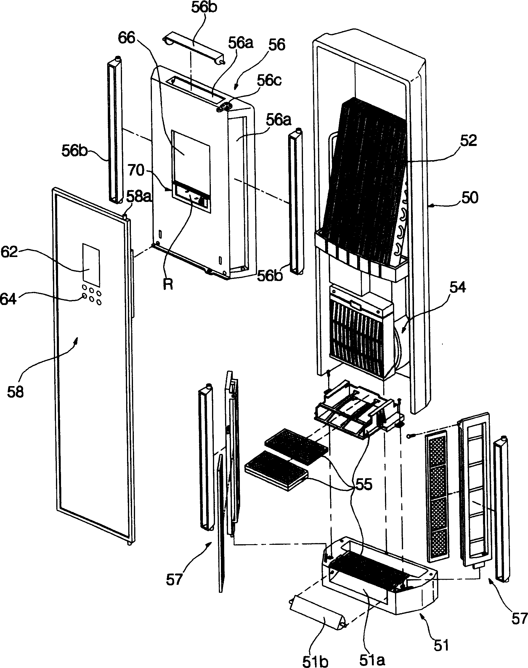
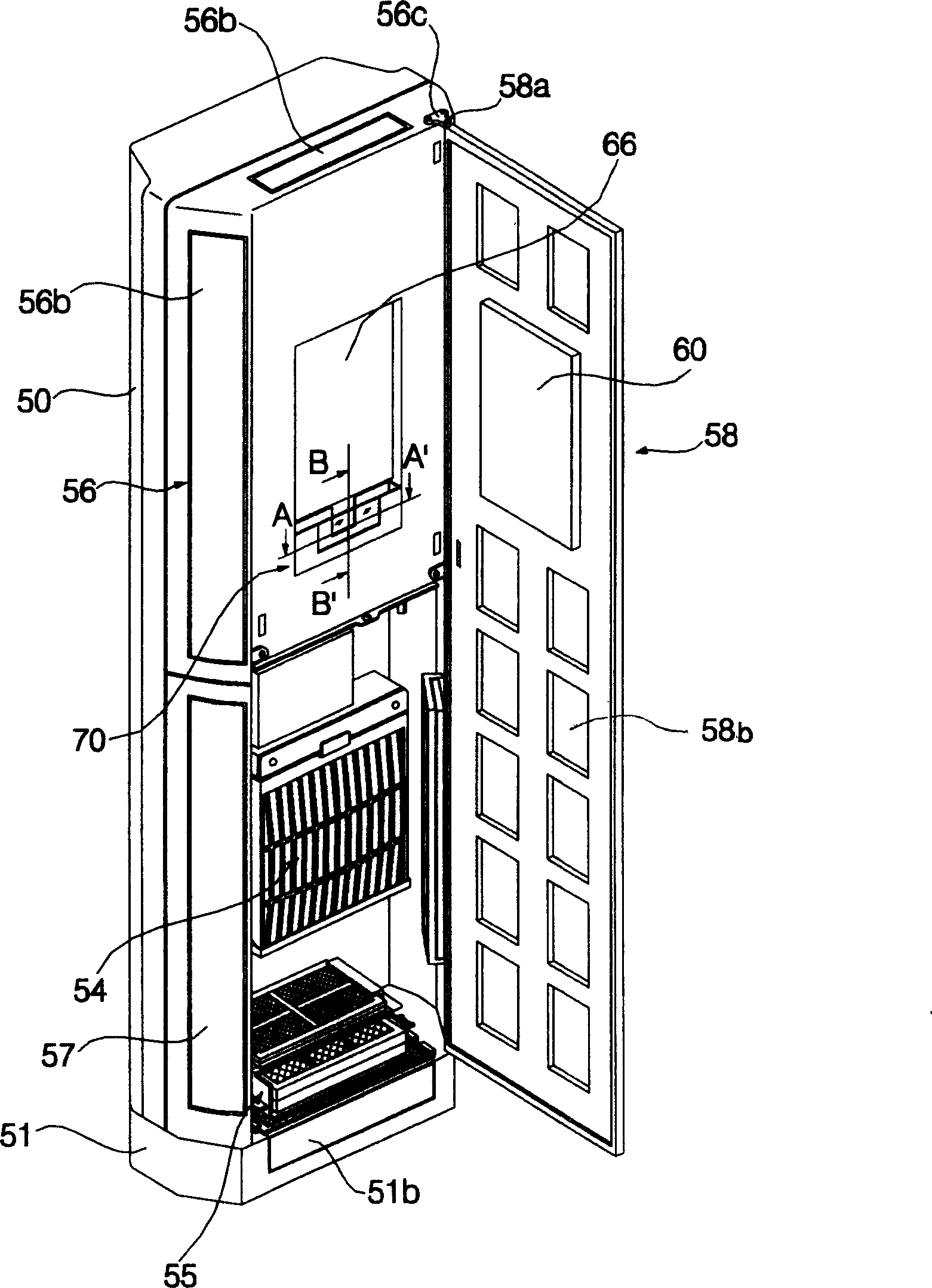
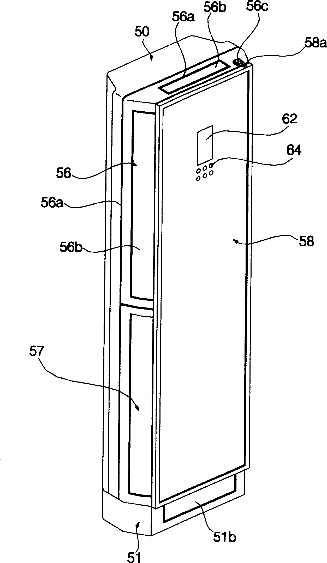
[0033] figure 1 It is an exploded perspective view of the indoor unit of the air conditioner of the present invention, figure 2 It is a perspective view of the open state of the front outer panel of the air conditioner indoor unit of the present invention, image 3 It is a perspective view of the closed state of the front outer panel of the indoor unit of the air conditioner of the present invention, Figure 4 It is a partial perspective view of the rotating state of the remote control storage box of the present invention, Figure 5 Yes figure 2 The A-A' line profile, Image 6 Yes figure 2 The B-B' line profile.

[0034] The indoor unit of the air conditioner of the present invention is as Figure 1 to Figure 6 As shown, it includes a casing 50 installed on the upper side of the chassis 51, and a built-in heat exchanger 52 and a blower 54 a...


PUM


Abstract

This invention relates to indoor unit of air conditioner. It includes a casing, which is at the upper side of basal plate and the anterior surface is opened. The heat exchanger and air-supplying machine position in the casing. The anterior surface inner sideboard is set at the upside of the opened anterior surface of casing. The anterior surface outer sideboard is set at front of the anterior surface inner sideboard. The space part is on the anterior surface inner sideboard and takes in the remote controller.

Description

technical field [0001] The invention belongs to the field of air conditioning, and in particular relates to an indoor unit of an air conditioner, especially related to an indoor unit of an air conditioner in which an openable and closable front panel is installed on the front inner panel and a remote controller is kept on the front inner panel . Background technique [0002] Figure 7 It is a perspective view of the closed state of the air outlet of the indoor unit of the prior art air conditioner, Figure 8 It is a perspective view of the open state of the air outlet of the indoor unit of the prior art air conditioner, Figure 9 It is the front view of the open state of the air outlet of the indoor unit of the prior art air conditioner, Figure 10 It is an exploded perspective view of an indoor unit of an air conditioner in the prior art. [0003] Air conditioner indoor unit of prior art such as Figure 7 to Figure 10 As shown, it includes a chassis 1; a casing 2 instal...

Claims


Application Information

Patent Timeline
Patent Type & Authority Applications(China)
IPC IPC(8): F24F1/00
Inventor 安民
Owner LG ELECTRONICS (TIANJIN) APPLIANCES CO LTD
Why Eureka
Try Eureka