Furniture hinge with spring

A technology for hinges and furniture, applied in the field of spring hinges, to achieve low-cost effects

Active Publication Date: 2007-01-31
ARTURO SALICE
View PDF3 Cites 8 Cited by
  • Summary
  • Abstract
  • Description
  • Claims
  • Application Information

AI Technical Summary

Problems solved by technology

[0007] In the known technology, there is no spring device that can give the hinge a thrust in the opening direction when the door is in the closed position

Method used


Image

  • Furniture hinge with spring
  • Furniture hinge with spring
  • Furniture hinge with spring

Examples


Embodiment Construction

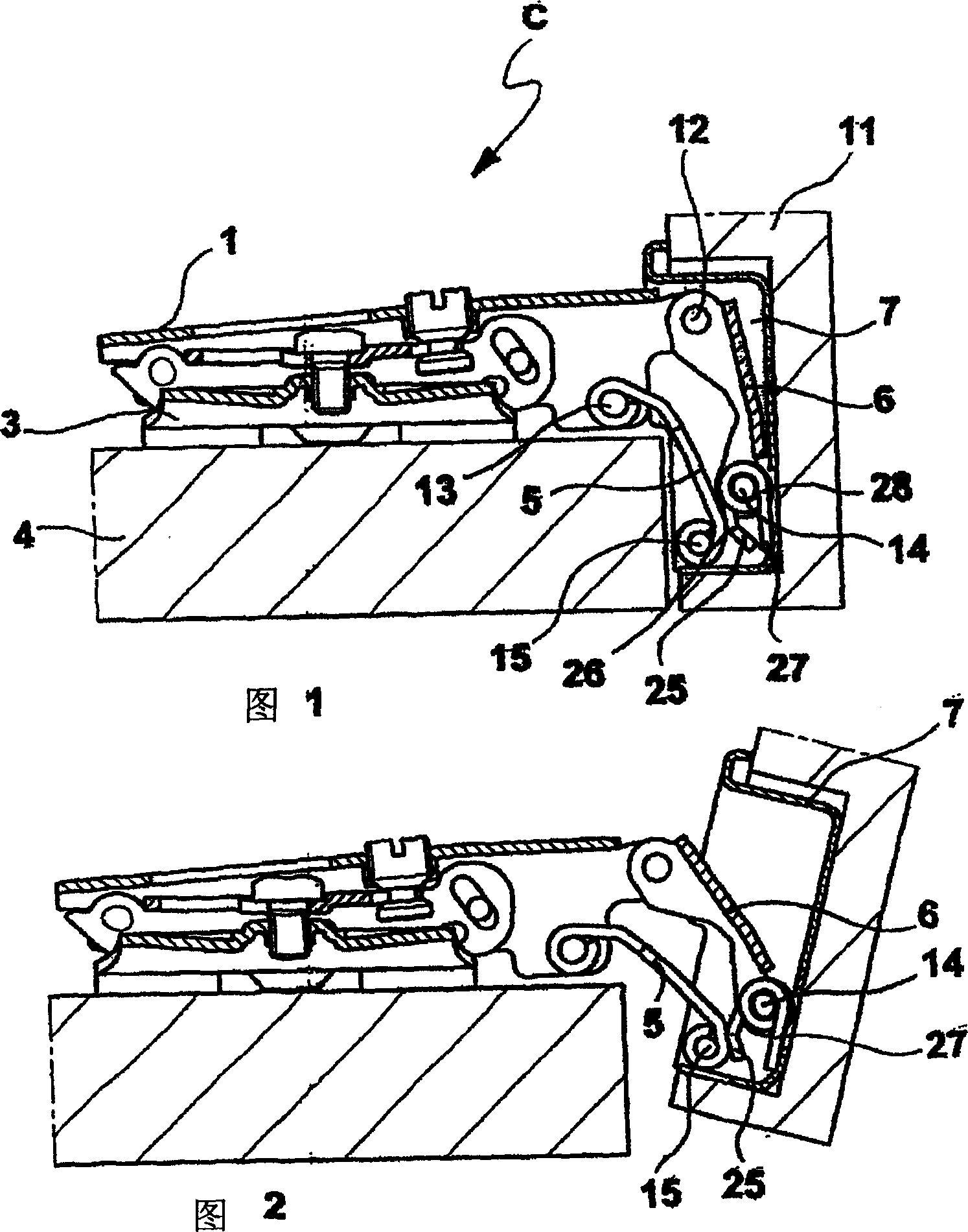
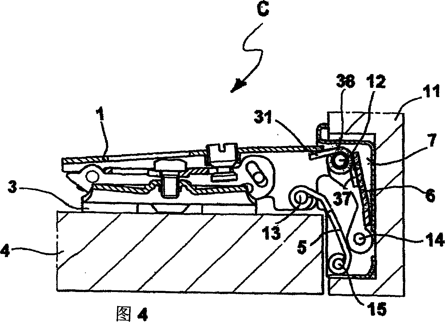
[0026] Referring to the attached drawings, the hinge is shown, indicated generally by the letter C. Said hinge comprises a fixed part or hinge arm 1 (which may be attached to a base) or a plate 3 which is integrally fixed to a supporting wall 4, such as a side of a piece of furniture or the like. The hinge C is provided with fastening and adjusting parts so that the arm 1 can be adjusted in 3 directions at right angles. As is known from the prior art, there are plates 2 for adjusting the hinge relative to the front and side directions of the furniture, the other vertical positions of which are not shown in detail in the figures.

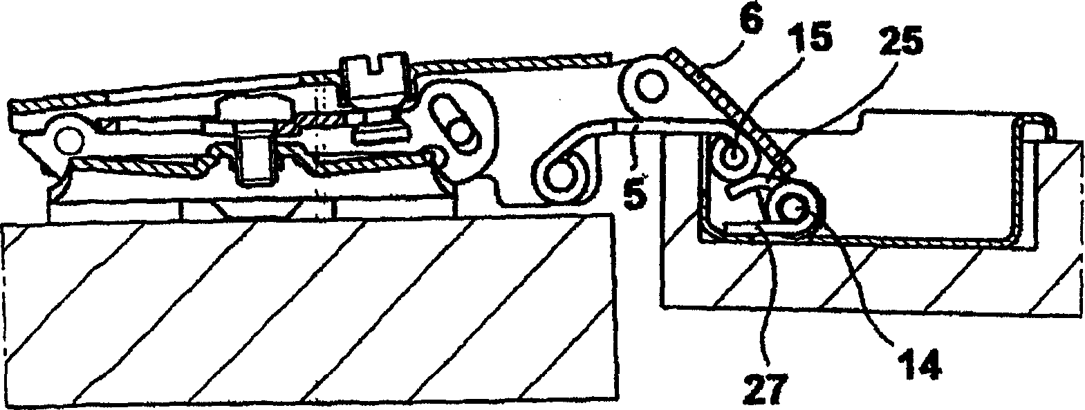
[0027] There are two rockers 5 , 6 each having a first end pivoting about two pins 12 , 13 housed in holes in the side wall of the arm 1 .

[0028] The arm 1 is connected to a box 7 which is fixed in a hole in the inner wall of a door 11 or other suitable pivoting part of the furniture. The respective second ends of the rockers 5 , 6 are housed in ...


PUM


Abstract

Furniture hinge with a fixing arm (1) for fixing to a piece of furniture (4), a member (7) for fixing to a door (11), linked by two rockers (5, 6), forming an articulated quadrilateral so as to allow the rotation thereof, a V-shaped spring (28, 38, 48), placed at an end of a rocker (6), with an arm of the spring resting on the member for fixing to the furniture (4) or to the door (11) and the other arm of the spring resting on one of the rockers (5, 6), so as to create a lever arm that compresses the spring (8) producing a moment in the opening direction of the door (11), when this is in the closed position.

Description

Technical field: [0001] The invention relates to spring hinges for doors or movable parts of furniture. Especially spring hinges that can apply a push force when opening. Background technique: [0002] Furniture for accommodating storage is usually equipped with doors or folding doors / leaves that can be opened and closed about a horizontal or vertical axis by a hinge mechanism. One common system is that the hinges holding the door in the closed position of the furniture are hidden when the door is closed. [0003] This hinge is widely used in the furniture industry due to several advantages that make it successful in the market. [0004] Known hinges are provided with different springs to create a return force when the door to which it is attached is closed. This solution allows precise closing of doors on furniture. However, such cases almost always require the application of external force to open the door of the furniture, which requires the use of different kinds of ...

Claims


Application Information

Patent Timeline
Patent Type & Authority Applications(China)
IPC IPC(8): E05F1/12E05D3/06E05D11/10
CPCE05D11/1064E05Y2900/20E05D3/142E05F1/1215E05D11/00E05F1/12E05D11/10E05D3/06
Inventor 卢西亚诺·塞莱斯
Owner ARTURO SALICE
Why Eureka
Try Eureka