Eureka AIR delivers breakthrough ideas for toughest innovation challenges, trusted by R&D personnel around the world.

Vehicle inertia gasoline economizer

A vehicle and inertial technology, applied in control devices, vehicle components, transportation and packaging, etc., can solve problems such as clutch wear and failure to shift gears

Inactive Publication Date: 2007-02-07
任明琪
View PDF0 Cites 2 Cited by
  • Summary
  • Abstract
  • Description
  • Claims
  • Application Information

AI Technical Summary

Problems solved by technology

At this time, if the accelerator is not well grasped, the clutch will wear out at an accelerated rate, and sometimes the back seat of the vehicle (engine braking) or the situation that the gear cannot be shifted will occur.

Method used


Image

  • Vehicle inertia gasoline economizer
  • Vehicle inertia gasoline economizer
  • Vehicle inertia gasoline economizer

Examples


Embodiment Construction

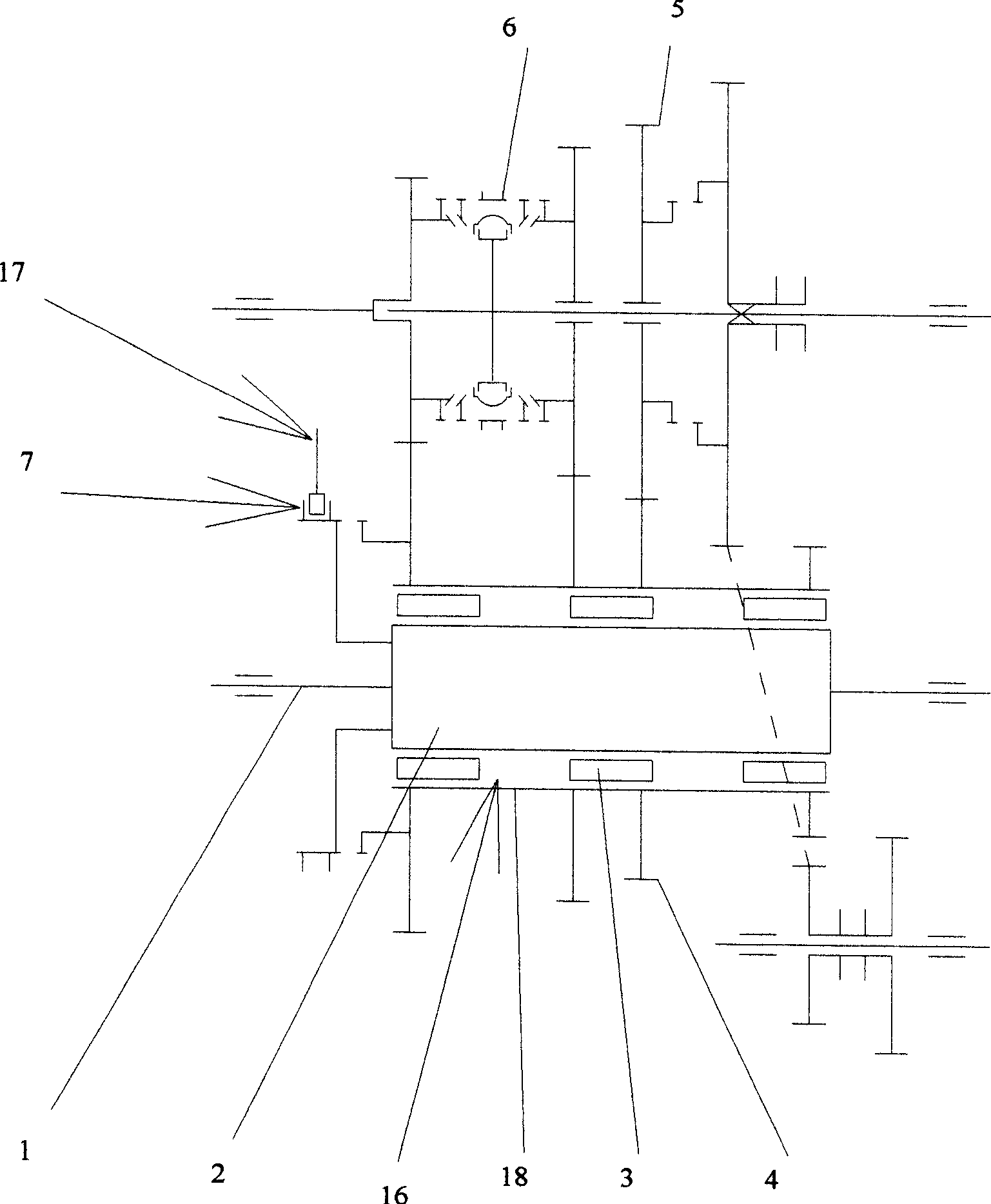
[0010] The embodiments of the present invention will be described below based on the drawings. figure 1 Shown is the transmission diagram of the transmission of this embodiment. In the figure, 1 is the input shaft of the transmission, 2 is the runner connected to the input shaft 1 by spline or other means, 3 is the friction roller, and 4 is the driving gear of the transmission. , 5 is a passive gear, 6 is a synchromesh, 7 is a locking device, and 17 is a locking operating device.

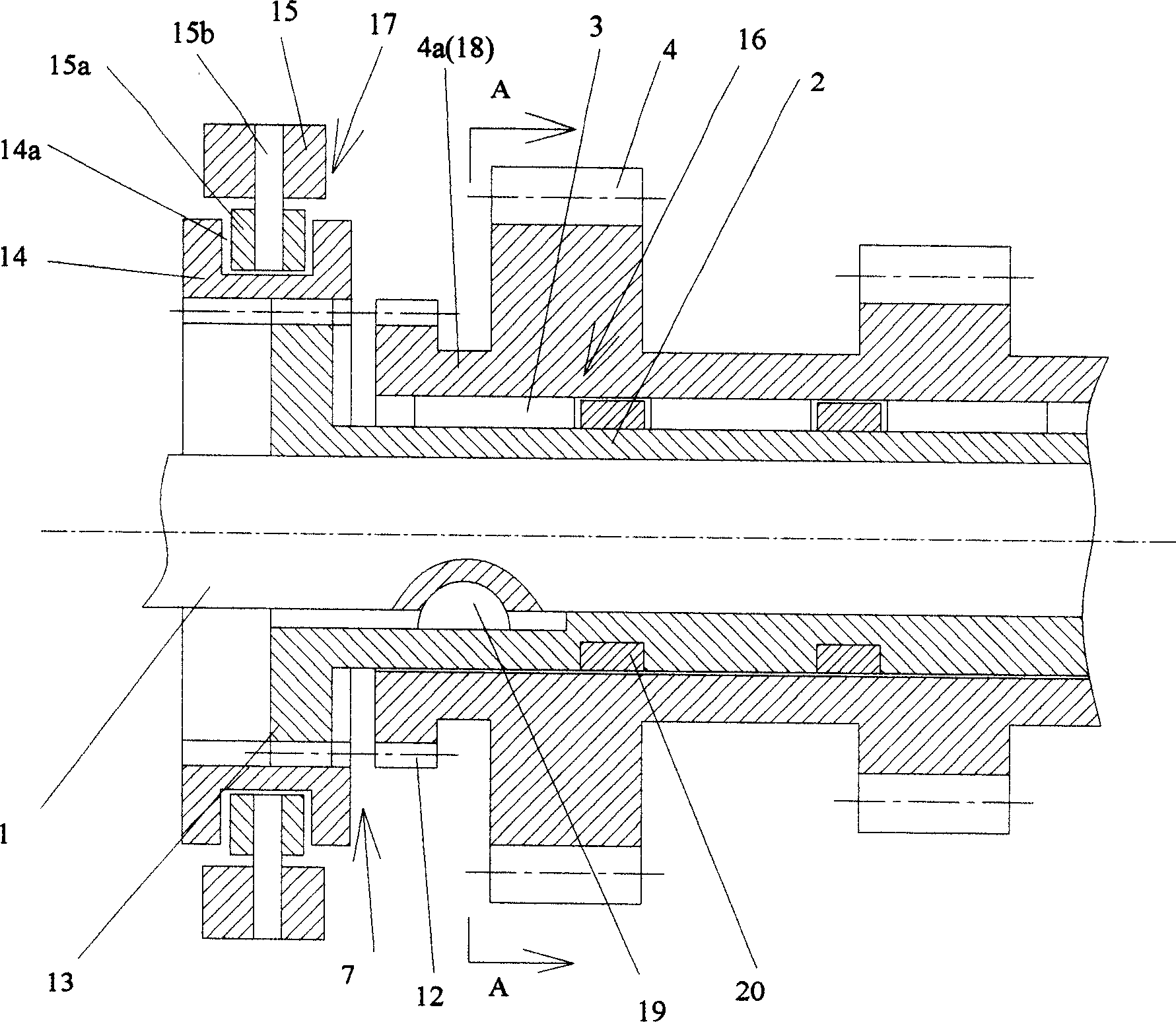
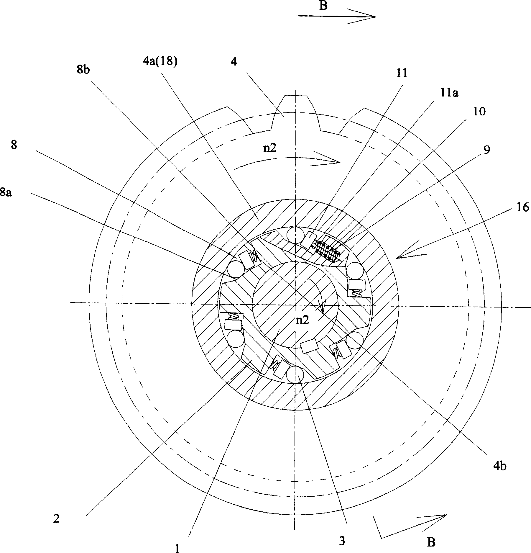
[0011] figure 2 It is the edge of the vehicle inertial fuel-saving device of the present invention image 3 A longitudinal cross-sectional view of the B-B line (schematic diagram), image 3 It is the edge of the vehicle inertial fuel-saving device of the present invention figure 2 A transverse cross-sectional view taken along the line A-A (a schematic diagram of the structure).

[0012] Such as figure 2 with image 3 As shown, in fact, the runner 2, the friction roller 3, the inner ring 4a of the d...


PUM


Abstract

The invention relates to a vehicle inertia fuel-saving device mounted on the transmission system of vehicle, wherein said fuel-saving device comprises: a one-way overrun clutch 16, a lock device 7, and a lock operator 17; the rotation speed ratio transmitted from the engine to the input 2 of one-way overrun clutch 16 is lower than the rotation speed ratio transmitted from the wheel to the output 18 of overrun clutch 16, the input 2 will not transmit torque to the output 18; the input 2 and the output 18 rotate relatively; when the rotation speed transmitted from the engine to the input 2 is increased to be same as the rotation speed transmitted from the wheel to the output 18, the overrun clutch 16 will automatically combine, and the torque of input 2 will be transmitted backwards via the overrun clutch 16; and when demanding the input 2 and the output 18 rotate at the same speed all the time, via operating the lock operator 17, the lock device 7 will lock the overrun clutch 16.

Description

Technical field [0001] The invention relates to a vehicle inertial fuel-saving device, in particular to a vehicle inertial fuel-saving device installed on a vehicle driveline and used for engine idling coasting to save fuel. Background technique [0002] In the past, the vehicle drive train was mainly composed of clutch, transmission, transfer case, transmission shaft, reducer, differential, half shaft and side reducer. Depending on the purpose or function of the vehicle, sometimes the drive train of a vehicle is composed of only some parts. Such a vehicle must engage neutral gear or step on a clutch when the engine is idling and the vehicle is coasting in neutral for fuel saving. When the idle gear is put into neutral gear or the idle speed is over on the clutch and the engine needs to be driven again, the clutch must be reconnected after shifting or not shifting. At this time, if the throttle is not well controlled, the clutch will wear out at an accelerated rate, and sometimes...

Claims


Application Information

Patent Timeline
Patent Type & Authority Applications(China)
IPC IPC(8): B60K17/26
Inventor 张恩任明琪
Owner 任明琪
Why Eureka
Eureka Blog
Learn More