System and method for auto-ignition of gasoline internal combustion engine

a technology of internal combustion engine and system, which is applied in the direction of machines/engines, electric control, output power, etc., can solve the problems of limiting the range at which an engine can be operated with a lean air/fuel mixture, the inability to apply knocking avoidance to the compression ignition of gasoline fuel, and the difficulty in achieving auto-ignition

Inactive Publication Date: 2002-05-14
NISSAN MOTOR CO LTD
View PDF9 Cites 128 Cited by
  • Summary
  • Abstract
  • Description
  • Claims
  • Application Information

AI Technical Summary

Problems solved by technology

There is however a limit at which an engine can be operated with a lean air / fuel mixture because of misfire and combustion instability as a result of a slow burn.
In four-stroke engines, because the residual content is low, auto-ignition is more difficult to achieve, but can be induced by heating the intake air to a high temperature or by significantly increasing the compression ratio.
This knocking avoidance technique cannot be applied to compression ignition of gasoline fuel that has a low cetane number.

Method used


Image

  • System and method for auto-ignition of gasoline internal combustion engine
  • System and method for auto-ignition of gasoline internal combustion engine
  • System and method for auto-ignition of gasoline internal combustion engine

Examples


Embodiment Construction

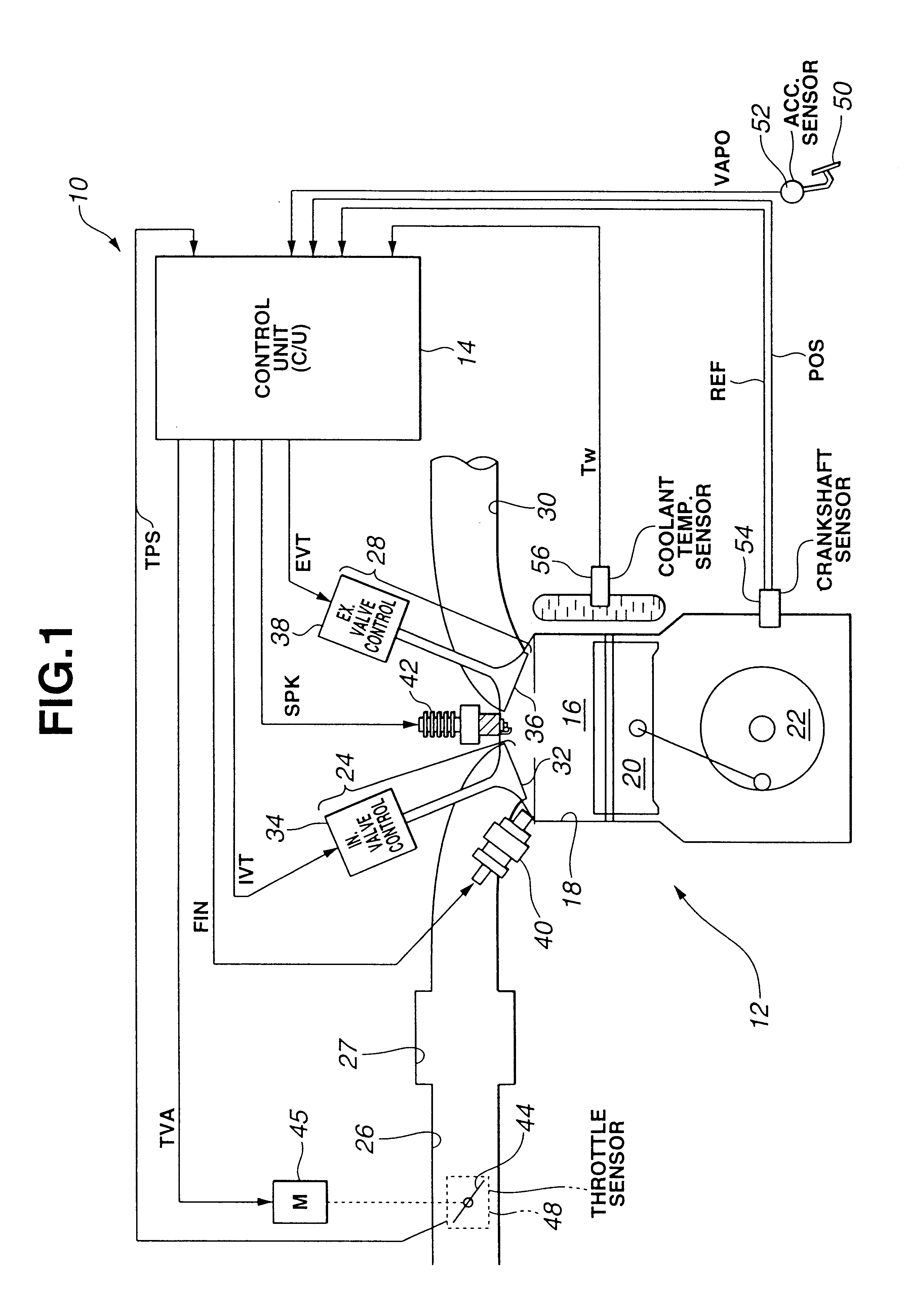
FIG. 1 is a block diagram illustrating operation of a system or method for controlling the fuel injection timing, the engine valve timing, and the ignition of a gasoline internal combustion engine during selection of one of a gasoline reform auto-ignition combustion mode, an auto-ignition stratified charge combustion mode, an auto-ignition homogeneous charge combustion mode, and a spark-ignition homogeneous charge combustion mode. System 10 includes an internal combustion engine, indicated generally by reference numeral 12, in communication with a control unit (C / U) 14. As schematically shown in FIG. 1, engine 12 has at least one combustion chamber 16 defined within a cylinder 18 by a reciprocating piston 20 operatively connected to a crankshaft 22. Combustion chamber 16 is provided with intake means 24 together with an intake manifold 26, including a collector 27, and exhaust means 28 together with an exhaust manifold 30. For admitting fresh air into combustion chamber 16, intake m...


PUM


Abstract

During operation with part load, a gasoline internal combustion engine is operated with a lean air / fuel mixture by auto-ignition. During operation with full load, spark-ignition is used to operate the engine. The internal combustion engine is operated in three auto-ignition combustion modes depending upon magnitude of a predetermined operating parameter. The operating parameter is indicative of the engine load or the engine speed. The three auto-ignition combustion modes are a gasoline reform auto-ignition combustion mode, an auto-ignition stratified charge combustion mode, and an auto-ignition homogeneous charge combustion mode. In the gasoline reform auto-ignition combustion mode that may be selected during operation with low part load, a first fuel injection during an exhaust gas retaining phase produces sufficient amount of active fuel radicals for promotion of auto-ignition of air / fuel mixture produced by a second fuel injection during the subsequent compression phase. In the auto-ignition stratified charge combustion mode that may be selected during operation with intermediate part load, a fuel injection during compression phase supports auto-ignition. In the auto-ignition homogeneous charge combustion mode that may be selected during operation with high part load, a fuel injection during intake phase supports auto-ignition.

Description

1. Field of the InventionThe present invention relates to a system and a method for an auto-ignition of gasoline internal combustion engine that runs under lean burn and controlled auto-ignition combustion conditions during operation with part load.2. Description of Related ArtTo improve thermal efficiency of gasoline internal combustion engines, lean burn is known to give enhanced thermal efficiency by reducing pumping losses and increasing ratio of specific heats. Flatly speaking, lean burn is known to give low fuel consumption and low NOx emissions. There is however a limit at which an engine can be operated with a lean air / fuel mixture because of misfire and combustion instability as a result of a slow burn. Known methods to extend the lean limit include improving ignitability of the mixture by enhancing the fuel preparation, for example using atomized fuel or vaporized fuel, and increasing the flame speed by introducing charge motion and turbulence in the air / fuel mixture. Fina...

Claims


Application Information

Patent Timeline
Patent Type & Authority Patents(United States)
IPC IPC(8): F02B17/00F02D13/02F02D41/30F02D41/40F02B75/12F02B75/02F02B1/12F02M25/07F02B1/00F02B75/00F02B11/00F02D41/02F02D41/04F02D41/38
CPCF02D13/0211F02D13/0253F02D13/0265F02D41/006F02D41/3035F02D41/3047F02D41/401F02D41/402F02M25/0752F02B17/005F02B1/12Y02T10/47F02B2075/025F02B2075/125F02D2013/0292F02D2041/001Y02T10/12Y02T10/128Y02T10/18Y02T10/44Y02T10/123F02M26/01Y02T10/40
Inventor URUSHIHARA, TOMONORIHIRAYA, KOJI
Owner NISSAN MOTOR CO LTD
Why Eureka
Try Eureka