

Coalescer for hydrocarbons containing surfactant
a technology of surfactant and coalescer, which is applied in the direction of cartridge filter, filtration separation, separation process, etc., can solve the problems of emulsion making coalescence very difficult, affecting the performance of the product, and contaminating the hydrocarbon fluid
- Summary
- Abstract
- Description
- Claims
- Application Information
AI Technical Summary
Problems solved by technology
Method used
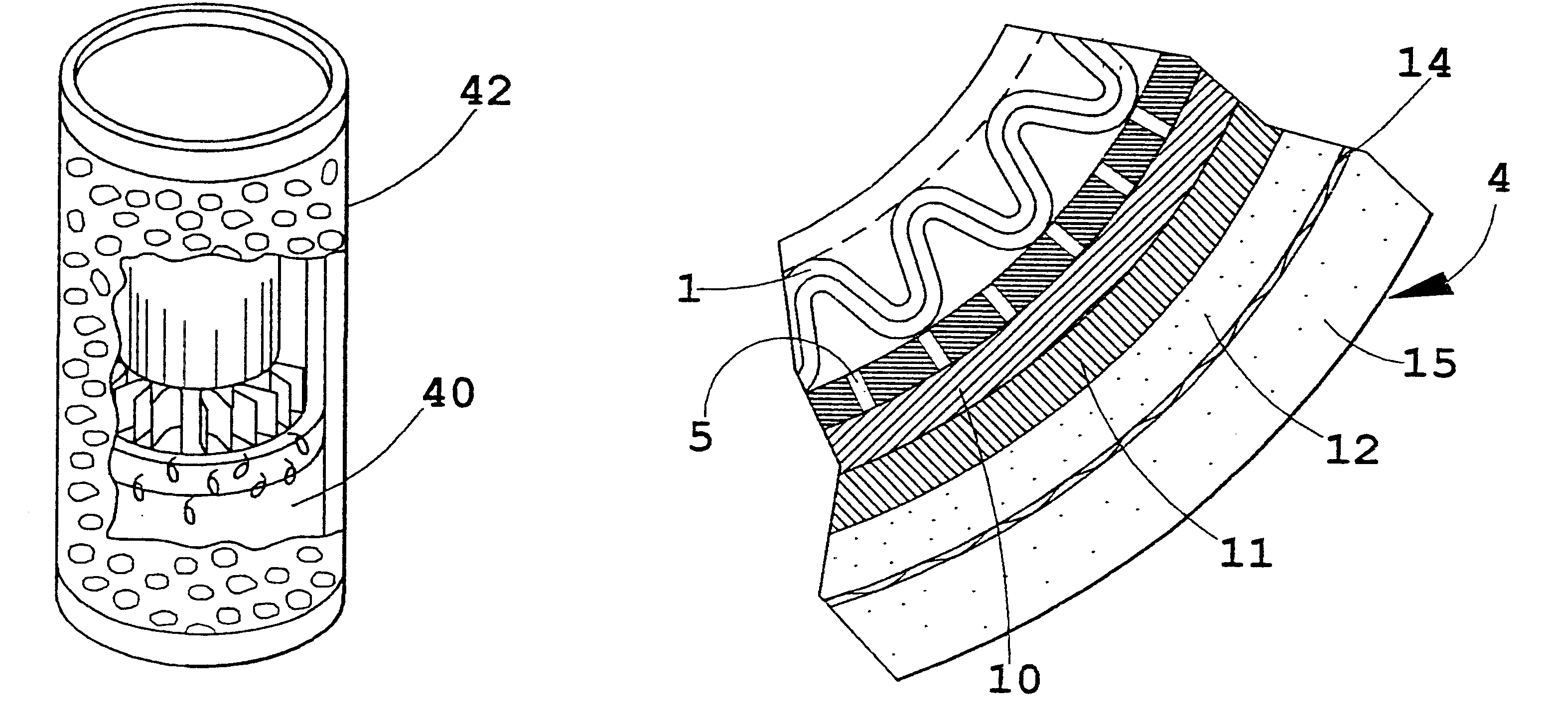
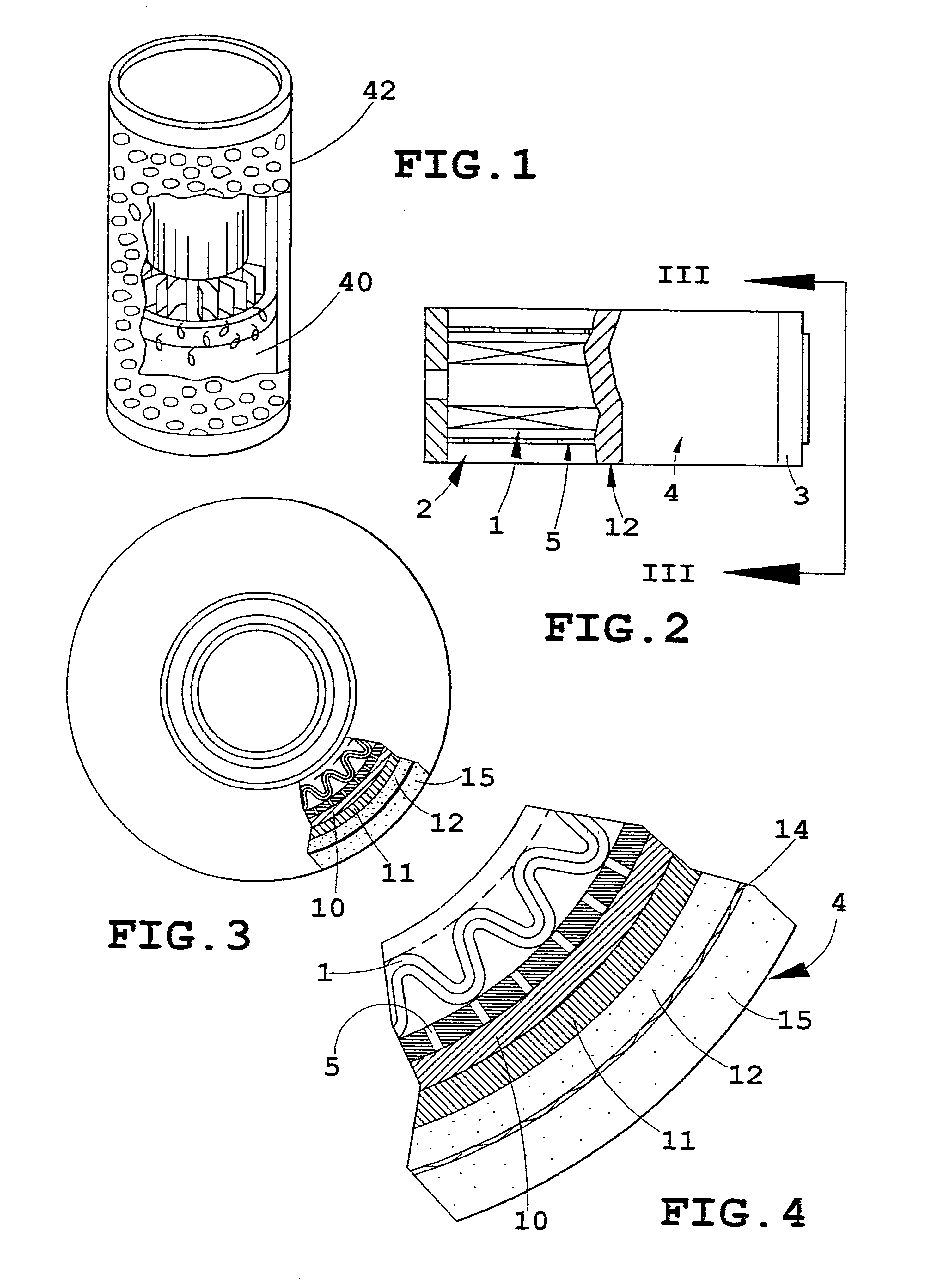
Image

Examples
example 2
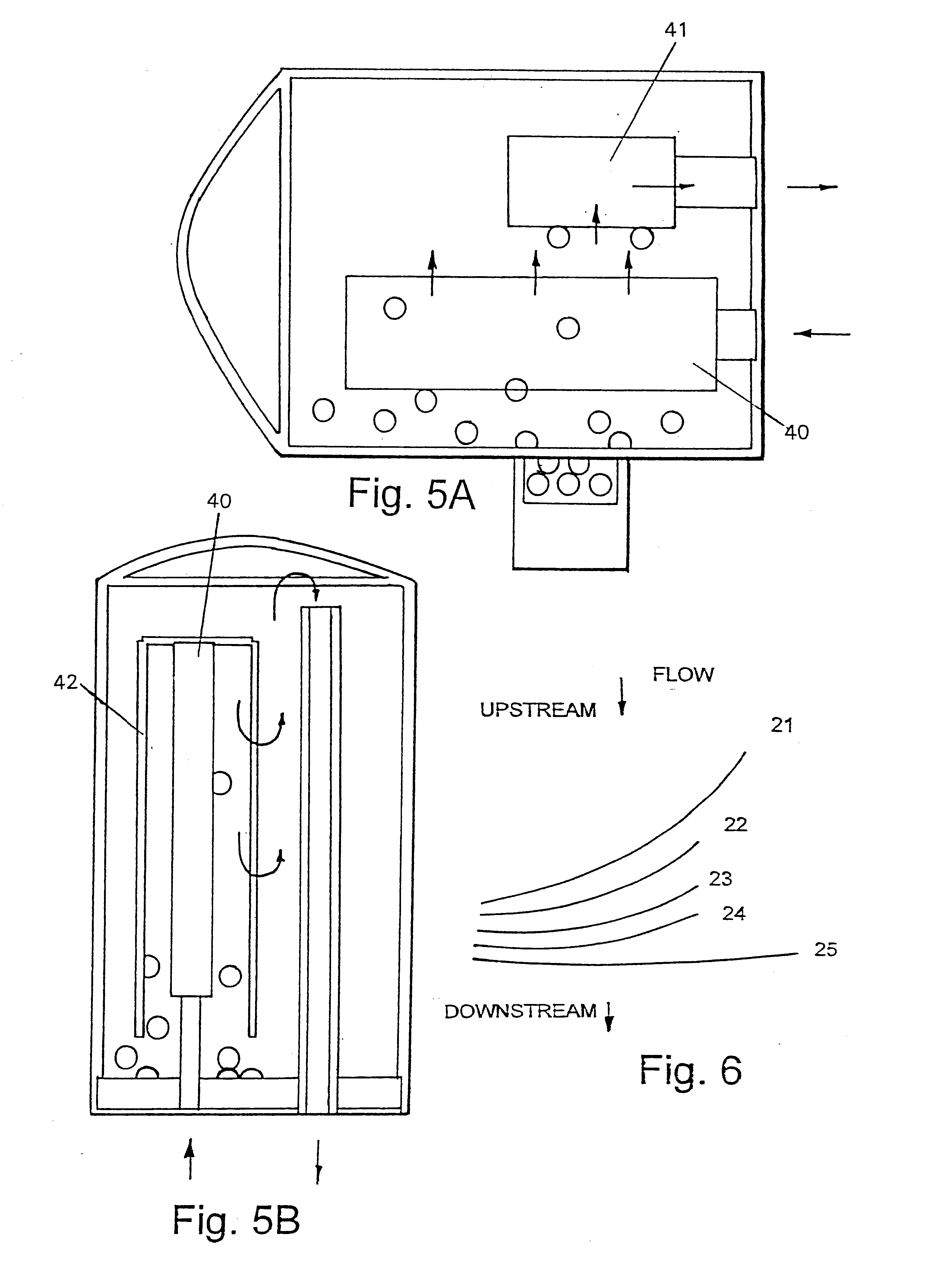
6".times.14" API style coalescer with 6.times.6 separate separator for API 1581 single element test. Both coalescer and separator were in horizontal configuration, as shown in FIG. 5A.
Single element tests for the coalescer at 33.44 gpm flow rate were conducted. The coalescer used in single element testing was 6".times.14" API style using gasket seals. The separator used for this testing was double open ended. The design parameters of the coalescer and separator are listed in Table 3. The test stand was built according to API 1581. The vessel containing coalescer and separator was constructed to simulate current API horizontal design as shown in FIG. 5A.
Additive package was added to clay treated jet fuel according to API 1581, Fourth Edition, section 4.2.4.2 for category M100 as follows. The mixing time was determined to be 20 mins. The fuel tank used for this testing was 250 gallon capacity. The amounts of additives are listed in Table 2. It is noted that additive SPEC AID 8Q462 man...
PUM
| Property | Measurement | Unit |
|---|---|---|
| Linear density | aaaaa | aaaaa |
| Kinematic viscosity | aaaaa | aaaaa |
| Kinematic viscosity | aaaaa | aaaaa |
Abstract
Description
Claims
Application Information