Portable hydrogen generator-fuel cell apparatus

a hydrogen generator and portable technology, applied in the direction of electric generators, transportation and packaging, chemical/physical/physicochemical processes, etc., can solve the problems of low hydrogen storage capacity, cryogenically adsorption of hydrogen on activated carbons not being suitable for portable devices, and being compact and light-weight sources

Inactive Publication Date: 2003-11-25
UNIV OF CENT FLORIDA RES FOUND INC +1
View PDF30 Cites 134 Cited by
  • Summary
  • Abstract
  • Description
  • Claims
  • Application Information

AI Technical Summary

Problems solved by technology

However, a compact FC would require a similarly compact and light-weight source of hydrogen.
Unfortunately, conventional means of storing hydrogen, including compressed gaseous or liquid hydrogen, as well as, hydrogen cryogenically adsorbed on activated carbons do not lend themselves to use in portable devices.
Similarly, the advanced methods of hydrogen storage, such as metal hydrides, catalytically enhanced metal hydrides, carbon nanotubes, also result in relatively low hydrogen storage capacities (below 6 w.
The common disadvantages of these systems based on hydrolysis of metal hydrides is the necessity to carry water and, most importantly, the requisite use of expensive metal hydrides which are irreversibly hydrolyzed into metal hydroxides during hydrogen production.
Thus, these systems would require handling of metal hydroxide slurries, which would be very difficult, energy intensive and costly to convert back to original hydride form.
The system also requires a large number of heat exchangers, compressors, valves, etc.
The steam reforming (SR) process requires a source of water which adds to the weight of the system.
This would result in a bulky system potentially difficult to miniaturize.
All these apparatuses are complex and bulky and suffer from the same disadvantages as the previous one.
The process is multi-stage, complex and would require an additional source of water.
However, the apparatuses are complex and require to carry a significant amount of water (e.g. in the first patent, 2-4 moles of steam per mole of carbon in the fuel) (although, some amount of water from the exhaust of FC could be recycled to the reactor).
There are several disadvantages common to all these integrated hydrogen generator-SOFC systems.
First of all, very high operating temperatures at which SOFC operate (approx. 1000.degree. C.) make them inconvenient for incorporation into small hand-held or other portable devices.
The use of heavier hydrocarbon feedstocks (gasoline, diesel fuel, etc.) might promote excessive hydrocarbon cracking reactions causing carbon deposits on the catalytic surfaces, and clogging interstices within the reactor bed.
Fourthly, a significant amount of water might be necessary to drive the reformation reaction and to prevent from coke deposits inside the integrated system.
Lastly, they may not be suitable for military applications, since they have an acoustic, thermal, and chemical (CO.sub.2) "signatures".
However, hydrogen was contaminated by carbon oxides which required additional purification step.
Thus, the whole process runs in a non-steady state regime using complex gas distribution and reagent delivery system.
Due to cyclic nature of the process, hydrogen is contaminated with carbon oxides which requires an additional stage of purification using methanator.
Furthermore, the above hydrogen generators utilize a number of moving parts, and produce large volumes of CO.sub.2 emissions.
However this apparatus operates at excessively high temperatures and would be very difficult to miniaturize due to its complexity.
Thus, diluted methane feedstock would result in a diluted hydrogen stream which could significantly reduce the efficiency of FC.
However, this would inevitably contaminate hydrogen with carbon oxides and require additional purification step.
There are several aspects of this invention that would make it very difficult to produce a compact device.
Most difficult is the transporting of a controllable amount of solid carbon from the bottom of the reaction chamber through a crushing device to the upper part of the chamber.
Secondly, it would be difficult to control the temperature gradient in the reaction chamber if a heat source other than electric coil will be used to drive the endothermic process.
Thirdly, the temperature in the upper part of the reaction chamber is 2000.degree. C., which could potentially affect the operation of a closely located membrane.
Lastly, the device has many moving parts (e.g. a centrifuge, a carbon crusher, a carbon transporter) which could make it bulky, noisy, and prone to malfunction.
Thus, both hydrogen and carbon constituents of the hydrocarbon fuel will be consumed by FC, resulting in high specific energy of the apparatus.
Scattering of carbon-product particles over the surface of oil spill results in breaking of the oil pellicle and formation of a plurality of oil / carbon isles separated from each other.

Method used


Image

  • Portable hydrogen generator-fuel cell apparatus
  • Portable hydrogen generator-fuel cell apparatus
  • Portable hydrogen generator-fuel cell apparatus

Examples


example 2

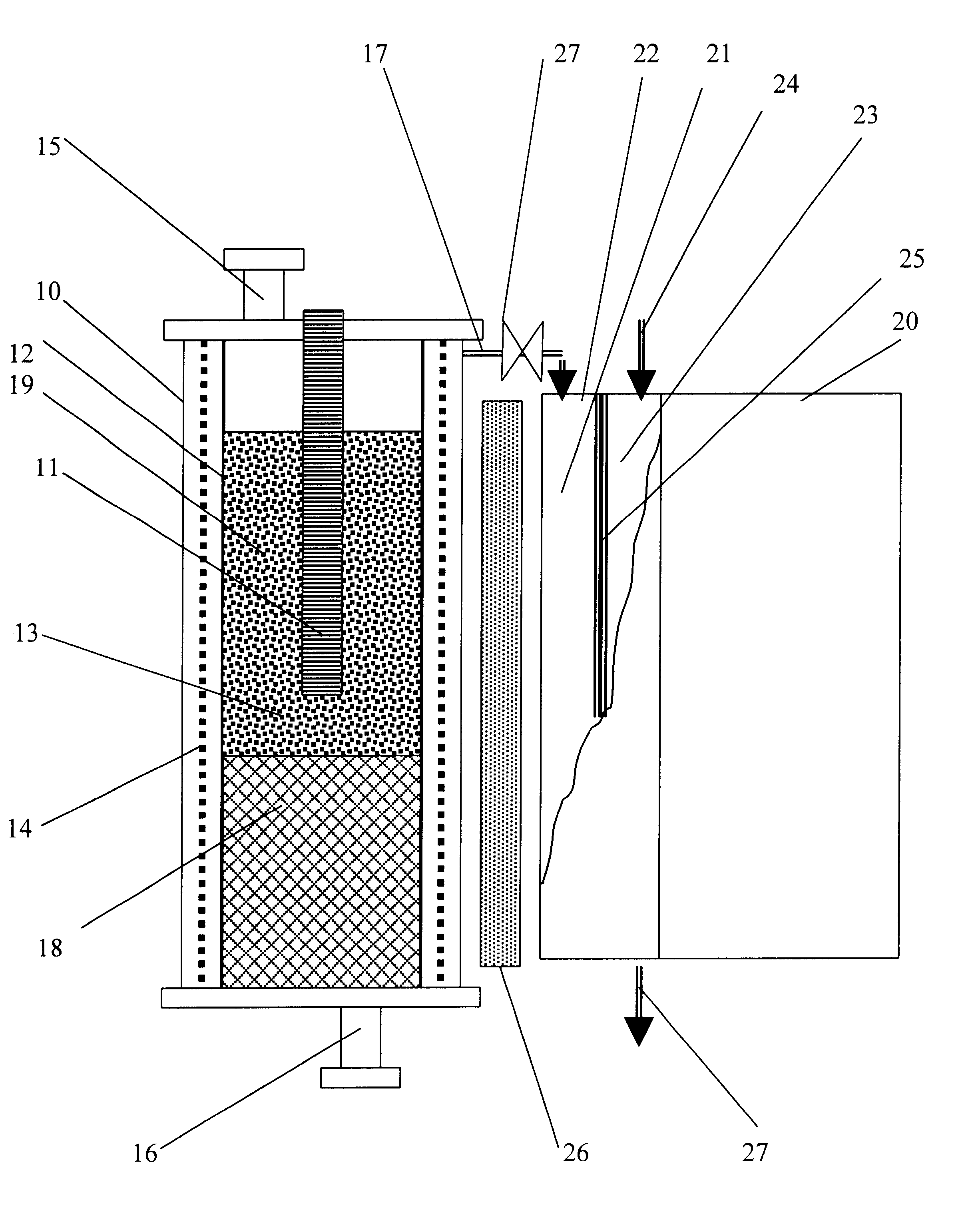
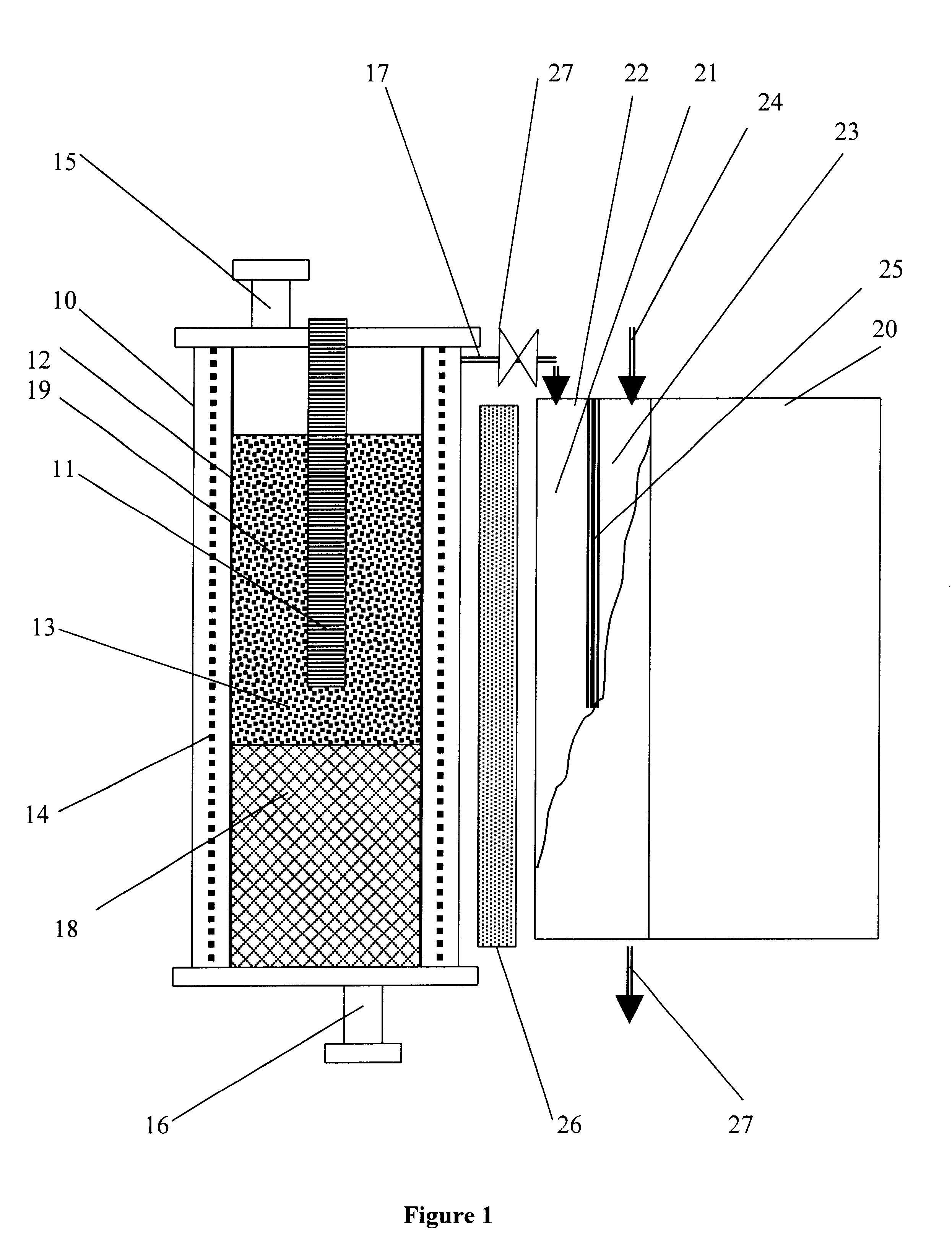
The experimental conditions of this experiment and the reactor were similar to the Example 1, except a ceramic fiber (volume 0.5 ml) was place at the bottom of the reactor and 0.41 g of diesel fuel was soaked into it. The reactor was maintained at 850.degree. C. 405 ml of gas with the average production rate of 10 ml / min was collected in the gas meter. The composition of the gaseous mixture was (vol. %): H.sub.2 -69.21, CH.sub.4 -30.21, C.sub.2 +-0.58.

examples 3-6

The following Table demonstrates other examples of the device operation using different CM and hydrocarbons at T=850.degree. C., P=1 atm, CM=0.5 g. Liquid hydrocarbons 0.2 g.

examples 7 and 8

demonstrate the feasibility of hydrocarbon decomposition over carbon-based ated by means of passing electric current through it.


PUM

PropertyMeasurementUnit
temperaturesaaaaaaaaaa
temperatureaaaaaaaaaa

Abstract

A compact hydrogen generator is coupled to or integrated with a fuel cell for portable power applications. Hydrogen is produced via thermocatalytic decomposition (cracking, pyrolysis) of hydrocarbon fuels in oxidant-free environment. The apparatus can utilize a variety of hydrocarbon fuels, including natural gas, propane, gasoline, kerosene, diesel fuel, crude oil (including sulfurous fuels). The hydrogen-rich gas produced is free of carbon oxides or other reactive impurities, so it could be directly fed to any type of a fuel cell. The catalysts for hydrogen production in the apparatus are carbon-based or metal-based materials and doped, if necessary, with a sulfur-capturing agent. Additionally disclosed are two novel processes for the production of two types of carbon filaments, and a novel filamentous carbon product. The hydrogen generator can be conveniently integrated with high temperature fuel cells to produce an efficient and self-contained source of electrical power.

Description

BACKGROUND AND PRIOR ARTRecent developments in fuel cell (FC) technology have resulted in compact, light-weight devices having the ability to continuously produce electrical power via electrochemical reactions involving an oxidant (usually, air) and a fuel (most preferably, hydrogen). These devices can potentially replace conventional batteries and are particularly useful for portable electronic systems, space and military (e.g. "soldier power") applications, transportation and other systems. However, a compact FC would require a similarly compact and light-weight source of hydrogen. Unfortunately, conventional means of storing hydrogen, including compressed gaseous or liquid hydrogen, as well as, hydrogen cryogenically adsorbed on activated carbons do not lend themselves to use in portable devices. Similarly, the advanced methods of hydrogen storage, such as metal hydrides, catalytically enhanced metal hydrides, carbon nanotubes, also result in relatively low hydrogen storage capac...

Claims


Application Information

Patent Timeline
Patent Type & Authority Patents(United States)
IPC IPC(8): H01M8/06B01J8/00B01J8/02B01J8/04B01J19/24C01B3/26
CPCB01J8/009B01J8/0221B01J8/025B01J8/0278B01J8/0285B01J8/0469B01J8/0492B01J8/0496B01J19/2475C01B3/26H01M8/0612H01M8/0662B01J8/0214Y10T428/2982B01J2208/00123B01J2208/00398B01J2208/00415B01J2208/00495B01J2208/00504B01J2208/025C01B2203/0277C01B2203/066C01B2203/0811C01B2203/085C01B2203/1041C01B2203/1058C01B2203/1247C01B2203/142Y02E60/50Y10T428/292Y10T428/30Y10T428/2918
Inventor MURADOV, NAZIM
Owner UNIV OF CENT FLORIDA RES FOUND INC
Why Eureka
Try Eureka