

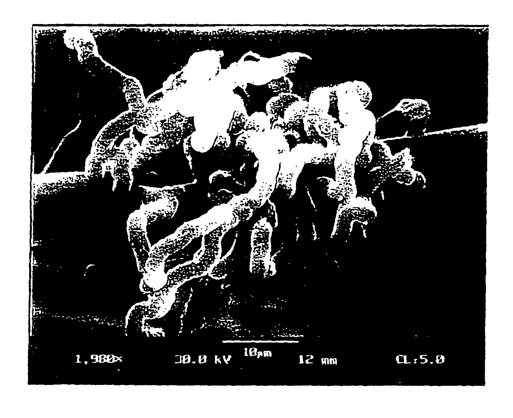
Filamentous carbon particles for cleaning oil spills and method of production
a technology of filamentous carbon particles and oil spills, which is applied in the direction of electrochemical generators, natural mineral layered products, cellulosic plastic layered products, etc., can solve the problems of low hydrogen storage capacity, low and conventional means of storing hydrogen, etc., to achieve the effect of increasing specific energy and overall energy efficiency of portable devices
- Summary
- Abstract
- Description
- Claims
- Application Information
AI Technical Summary
Benefits of technology
Problems solved by technology
Method used
Image

Examples
example 1
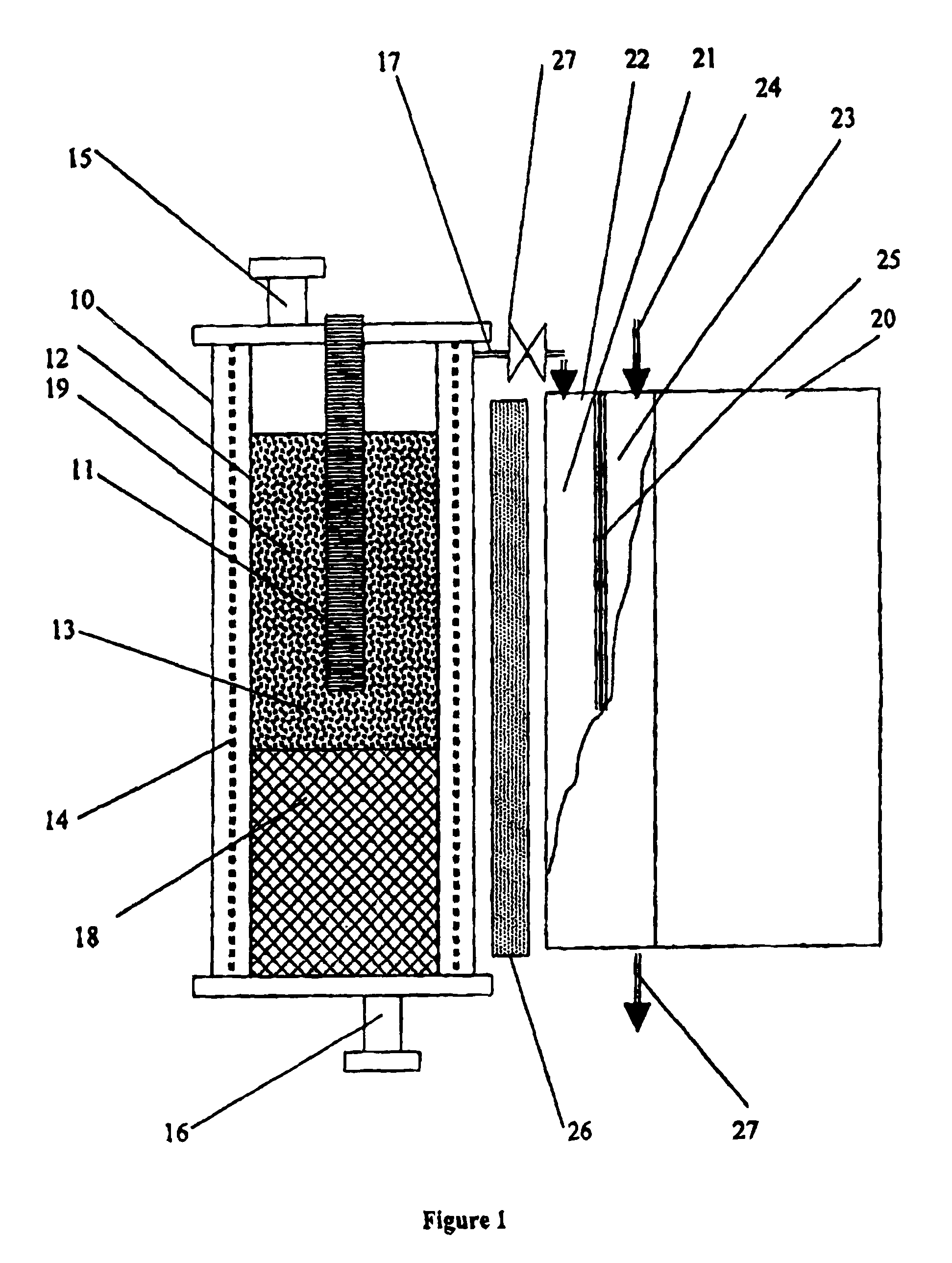
[0044]An activated carbon (CL-20 brand, produced from coconut shells by Barneby Sutcliffe Corp.) in the form of 1 mm granules with the surface area of 1650 m2 / g was used as a catalytic material. 0.5 g of AC was placed in a quartz tubular reactor (volume 5 ml) with closed end; the reactor was heated by the external electric heater to 500° C. and purged with an inert gas (Ar) using a thin (OD 1.6 mm) ceramic tubing reaching the bottom of the reactor in order to remove adsorbed water and entrained air from the catalyst. The reactor cooled to room temperature and 0.2 ml of gasoline was introduced to the bottom of the reactor using the same ceramic tubing such that it soaked into lower catalyst layer. The ceramic tubing was removed and the reactor connected to a gas meter. This was followed by heating the upper part of the catalyst layer to 850° C. and slowly moving a heater downward to the bottom of the reactor. The total of 148 ml of gas with the average production rate of 7.5 ml / min w...
example 2
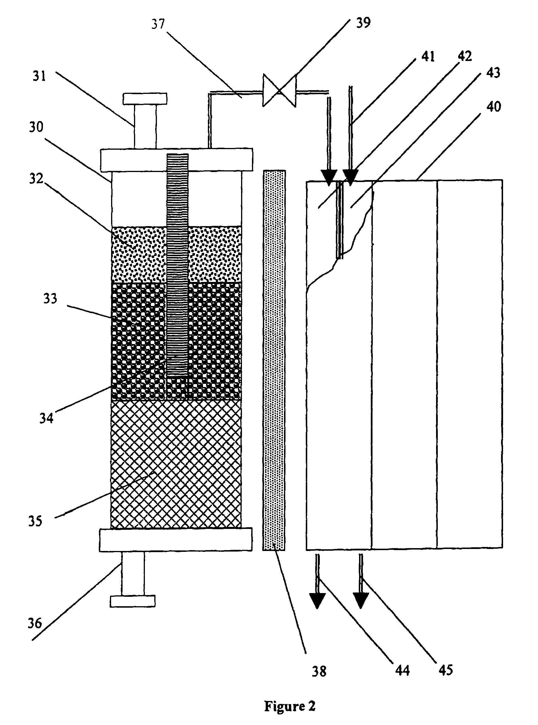
[0045]The experimental conditions of this experiment and the reactor were similar to the Example 1, except a ceramic fiber (volume 0.5 ml) was place at the bottom of the reactor and 0.41 g of diesel fuel was soaked into it. The reactor was maintained at 850° C. 405 ml of gas with the average production rate of 10 ml / min was collected in the gas meter. The composition of the gaseous mixture was (vol. %): H2—69.21, CH413 30.21, C2+—0.58.
examples 3-6
[0046]The following Table demonstrates other examples of the device operation using different CM and hydrocarbons at T=850° C., P=1 atm, CM=0.5 g. Liquid hydrocarbons 0.2 g.
[0047]
TABLE 1CatalyticHydro-Gaseous Products, vol. %ExampleMaterialcarbonH2CH4C2H6C2H4C3+3AC, CL-20Hexane80.7410.882.464.501.434AC, KBB*Iso-octane58.6931.360.972.536.455AC, KBBPropane**74.1518.941.402.183.326Fe (10 w %) / Gasoline82.1413.600.841.841.58Al2O3*KBB is AC produced from a hardwood by NURIT Americas**Equimolar amount of propane was introduced into the reaction zone via ceramic tubing
[0048]Examples 7 and 8 demonstrate the feasibility of hydrocarbon decomposition over carbon-based CM heated by means of passing electric current through it.
PUM
| Property | Measurement | Unit |
|---|---|---|
| mean diameter | aaaaa | aaaaa |
| diameter | aaaaa | aaaaa |
| temperatures | aaaaa | aaaaa |
Abstract
Description
Claims
Application Information