Cabinet air-conditioner indoor machine evaporation structure

An air conditioner indoor unit and evaporator technology, applied in heating methods, space heating and ventilation details, household heating, etc., can solve the problem of reducing the air conditioner's rapid cooling/heating ability, small heat exchange area, and occupation Small space and other issues, to achieve the effect of improving the ability of rapid cooling/heating and increasing the area of ​​heat exchange

Inactive Publication Date: 2007-02-07
LG ELECTRONICS (TIANJIN) APPLIANCES CO LTD
View PDF0 Cites 1 Cited by
  • Summary
  • Abstract
  • Description
  • Claims
  • Application Information

AI Technical Summary

Problems solved by technology

[0011] figure 1 , figure 2 , image 3 The evaporator 3 of the indoor unit of the cabinet type air conditioner shown in the prior art is a whole cuboid structure. When the evaporator is placed, it occupies a small space. There is a large amount of idle space in the cabinet machine, and the air sent by the centrifugal fan 4 flows through the evaporator. At 3 o'clock, only a small area of ​​cooling / heating can be carried out, that is to say, the entire cuboid structure of the evaporator in the indoor unit of the cabinet air conditioner of the prior art has a small area for heat exchange, and the cabinet has a large amount of idle space, which reduces the temperature of the air conditioner. Problems with rapid cooling / heating capabilities

Method used


Image

  • Cabinet air-conditioner indoor machine evaporation structure
  • Cabinet air-conditioner indoor machine evaporation structure
  • Cabinet air-conditioner indoor machine evaporation structure

Examples


Embodiment Construction

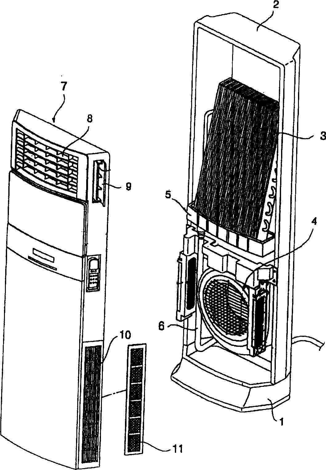
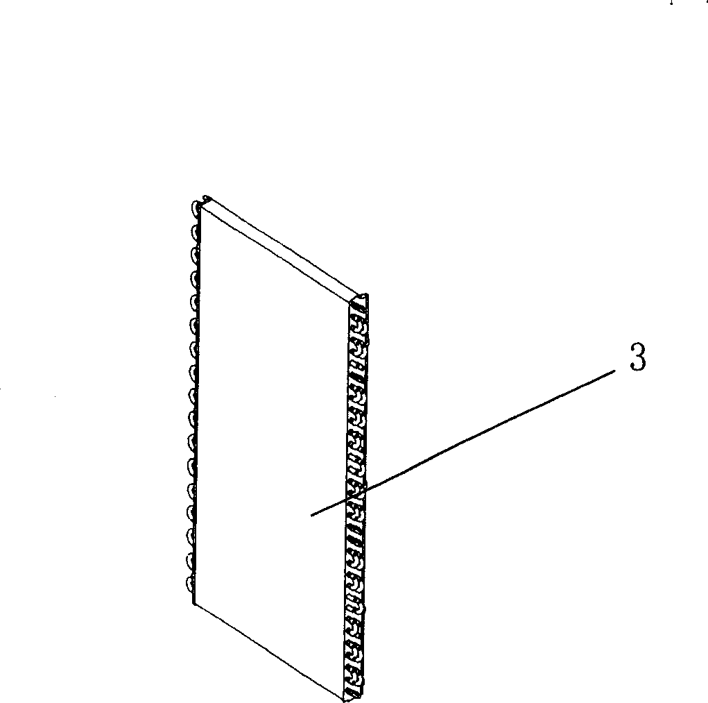
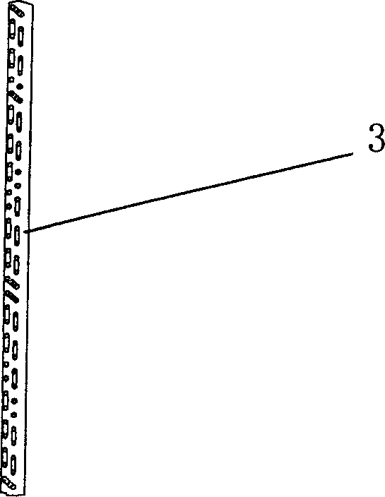
[0030] Figure 4 It is a schematic diagram of the evaporator structure of the cabinet air conditioner indoor unit of the present invention. Figure 5 It is a side view of the evaporator of the cabinet-type air conditioner indoor unit of the present invention. The improved structure of the indoor unit evaporator of the cabinet type air conditioner of the present invention will be further described with reference to the accompanying drawings.

[0031] The indoor unit structure of the cabinet type air conditioner of the present invention includes: a chassis 1, a cabinet 2 that is erected on the chassis 1 and has a front opening, and is connected to the front of the cabinet and has an air discharge port and an air suction port. The front panel 7 is an evaporator arranged in the upper part of the casing and between the casing 2 and the front panel 7, and a centrifugal fan 4 is arranged in the lower part of the casing. The lower part of the evaporator is placed in the water receiving tr...


PUM


Abstract

The present invention relates to an air conditioner technical field, especially a cabinet air-conditioner indoor machine evaporation structure, wherein the evaporator is disposed on the top of the conditioner shell and between the shell and the front panel. The evaporator is formed by a 'U-shape' copper pipe denting into uniformly arranged fins to be a integer with an arc upside and a straight tabular inferior, making full use of the unused space. The cabinet air-conditioner indoor machine evaporation improved structure of the invention increases the heat exchange area compared to the existing evaporator and advances the ability of the conditioner fast refrigeration/heating.

Description

Technical field [0001] The present invention relates to the technical field of air conditioners, in particular to the evaporator structure of an indoor unit of a cabinet type air conditioner. Background technique [0002] Generally speaking, an air conditioner is a refrigeration / heating device that keeps the indoor temperature at the temperature required by the user. The refrigerant circulating in its refrigeration system exchanges heat with the air flowing in the room to achieve indoor cooling or heating. People provide fresh and comfortable air environment. The refrigeration system of the air conditioner is mainly composed of an evaporator, a condenser, a compressor, and a throttling expansion device. [0003] In summer, the refrigerant in the refrigeration system performs a refrigeration cycle in the order of evaporation→compression→condensation→expansion to realize the cooling operation of the air conditioner; in winter, through the switching of the reversing valve, the refri...

Claims


Application Information

Patent Timeline
Patent Type & Authority Applications(China)
IPC IPC(8): F24F13/30
Inventor 许文斌
Owner LG ELECTRONICS (TIANJIN) APPLIANCES CO LTD
Why Eureka
Try Eureka