
Self-locking compact type vertical lifting mechanism

A vertical lifting mechanism, compact technology, applied in the direction of lifting frame, lifting device, etc., can solve the problems of occupying a large space, not being able to go straight up and down, high cost, etc., to achieve compact structure in the axial direction, safe lifting process, and stress-resistant reasonable effect

Inactive Publication Date: 2007-02-14
文德承
View PDF0 Cites 3 Cited by
  • Summary
  • Abstract
  • Description
  • Claims
  • Application Information

AI Technical Summary

Problems solved by technology

This kind of lifting mechanism needs to be equipped with an expensive hydraulic system, and the noise reduction technology of the hydraulic pump is complicated and the cost is very high; the L-shaped lever needs to swing a lot when lifting up and down, and it cannot be raised and lowered directly, which takes up a lot of space and affects the patient. comfort

Method used


Image

  • Self-locking compact type vertical lifting mechanism
  • Self-locking compact type vertical lifting mechanism
  • Self-locking compact type vertical lifting mechanism

Examples


Embodiment Construction

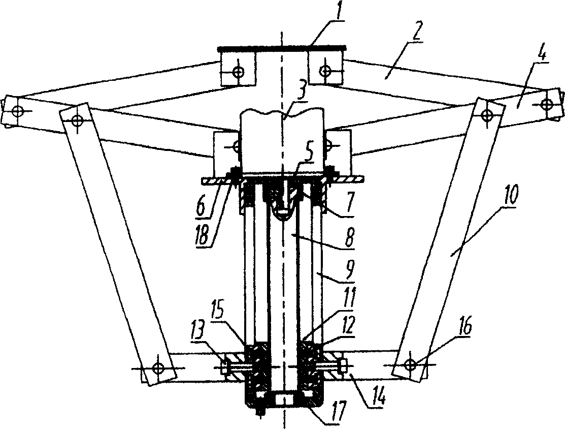
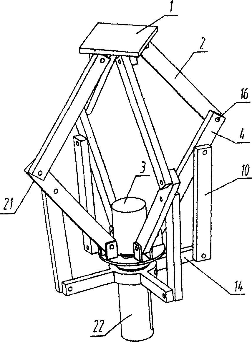
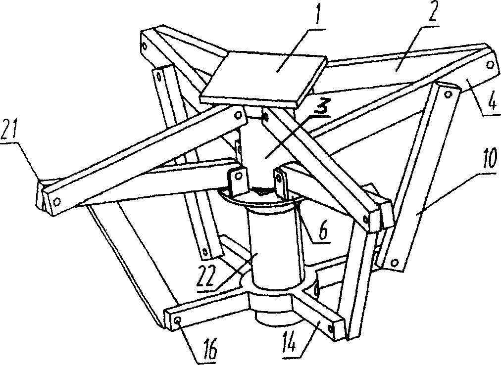
[0012] The present invention is described in further detail by the following examples.

[0013] see figure 1 , figure 2 , image 3 As shown, a self-locking compact vertical lifting mechanism of the present invention includes a link slider mechanism 21 , a screw nut mechanism 22 and a housing 9 . Described link slider mechanism 21 is made up of fixed plate 6, upper slider 1, lower slider 14 and four groups of rods, each group of rods includes upper connecting rod 2, lower connecting rod 10 and swing rod 4, each rod Both ends of the parts are provided with holes, and the upper and lower sliders 1, 14 and the fixed plate 6 are provided with corresponding hinge seats, and each hinge seat is correspondingly provided with a pin hole, which is hinged to each other through the pin shaft 16: the upper connecting rod The top of 2 is hinged to the bottom of upper slider 1, the bottom of upper connecting rod 2 is hinged to the top of swing rod 4, the top of lower connecting rod 10 is ...


PUM


Abstract

The present invention discloses one kind of self-locking compact vertical elevating mechanism capable of realizing great stroke vertical elevation within a narrow space and with relatively low production cost. The vertical elevating mechanism consists of a link rod-sliding block mechanism, a screw-nut mechanism and a casing. The screw-nut mechanism is set inside the casing, and the link rod-sliding block mechanism has fixing board connected to the top of the casing and lower sliding board connected to the screw-nut mechanism. The present invention is used mainly in treating bed and other rehabilitative medical equipment, and may be also used in other field needing great stroke vertical elevation in narrow space.

Description

technical field [0001] The invention relates to the technical field of vertical lifting mechanical devices, in particular to a self-locking compact vertical lifting mechanism. Background technique [0002] The existing mechanical lifting mechanism, especially the lifting mechanism used in the field of rehabilitation medical equipment, mostly adopts an L-shaped swinging lever mechanism, and the hydraulic device drives the lever to swing around the fulcrum on the base, so that the treatment bed and other rehabilitation equipment products The bed body and the patient above are lifted from a low position to a high position. This kind of lifting mechanism needs to be equipped with an expensive hydraulic system, and the noise reduction technology of the hydraulic pump is complicated and the cost is high; when the L-shaped lever is lifted and lowered, it needs to swing a lot, and it cannot be raised and lowered directly, which takes up a lot of space and affects the patient. comfo...

Claims


Application Information

Patent Timeline
Patent Type & Authority Applications(China)
IPC IPC(8): B66F7/00
Inventor 肖耘亚神翠楠文德承陈桂荣黄文熠罗永捷欧锦华
Owner 文德承
Learn More