Hollow component

A cavity and component technology, used in building components, building structures, floor slabs, etc., can solve problems such as large consumption of concrete

Inactive Publication Date: 2007-02-14
湖南邱则有专利战略策划有限公司
View PDF4 Cites 2 Cited by
  • Summary
  • Abstract
  • Description
  • Claims
  • Application Information

AI Technical Summary

Problems solved by technology

However, after this cavity component is applied to the hollow floor, the concrete consumption is still relatively large due to the large number of ribs. Therefore, it is urgently needed to develop a new type of cavity component.

Method used


Image

  • Hollow component
  • Hollow component
  • Hollow component

Examples


Embodiment Construction

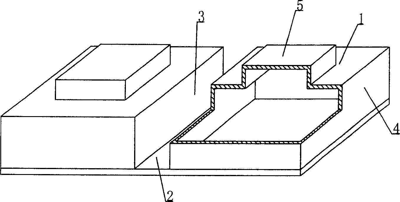
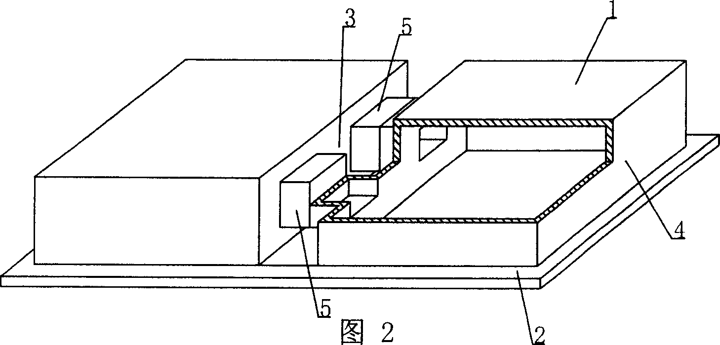
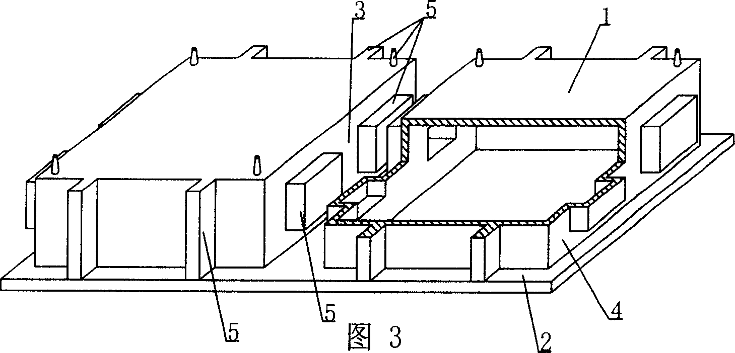
[0082] The present invention will be further described below in conjunction with the accompanying drawings and embodiments.

[0083] As shown in the accompanying drawings, the present invention includes a cavity formwork 1 and a bottom plate 2, the cavity formwork 1 and the bottom plate 2 are connected as a whole, and at least two cavity formworks 1 are arranged alternately on the bottom plate 2, and the sides thereof are connected to the bottom plate 2 Constitute at least one cast-in-place structure inner rib cavity 3, and the other outer side 4 of the cavity formwork 1 constitutes the side formwork of the cast-in-place structure outer rib or beam or wall, which is characterized in that the cavity formwork 1 is provided with The convex module 5 of the non-reinforcing rib that protrudes outwards is used to reduce the amount of concrete. The convex module 5 is arranged on the side formwork of the cavity formwork 1 of the inner rib cavity 3 of the cast-in-place structure, and the...


PUM


Abstract

A cavity component includes cavity die shell and base plate. It is featured as connecting said shell with base plate to form an integral unit, arranging at least two said shells on base plate alternatively, using cavity die shell side surface and base plate to form internal-rib die cavity with at least one cast-in-place structure and using the other external side surface of cavity die shell to form external-rib side template of cast-in-place structure, setting convex die block on side template of cavity die shell for decreasing use amount of concrete and projecting convex die block on opposite side template at the same opposite axle.

Description

[0001] This application is a divisional application of the invention patent application with the filing date of June 2, 2003, the application number of 03137263.5, and the title of "A Cavity Member". (1) Technical field [0002] The present invention relates to a cavity member. (2) Background technology [0003] At present, most buildings with brick-concrete structure and reinforced concrete structure use prefabricated hollow slabs as floor slabs, which have the advantages of fast construction speed and low cost. However, because there is no firm connection between two adjacent prefabricated hollow slabs, only cement mortar is used to fill the joints, so the integrity is poor, which is not conducive to earthquake resistance, and cracks and water seepage often occur in the gaps. In order to solve the above problems, many buildings adopt the method of cast-in-place concrete floor slabs (solid and hollow). Although the problems of earthquake resistance and cracking have been so...

Claims


Application Information

Patent Timeline
Patent Type & Authority Applications(China)
IPC IPC(8): E04B5/18E04B5/36
Inventor 邱则有
Owner 湖南邱则有专利战略策划有限公司
Why Eureka
Try Eureka