Pressure monitord by displacement type method for controlling fluid form machine for powder

A displacement monitoring and control method technology, which is applied in the direction of material forming presses, hydraulic controllers, presses, etc., can solve problems such as difficult control, brick pressure reduction, error, etc., to improve quality stability, facilitate installation and The effect of minor changes in maintenance and hardware structure

Active Publication Date: 2007-02-21
FOSHAN HENGLITAI MACHINERY
View PDF1 Cites 15 Cited by
  • Summary
  • Abstract
  • Description
  • Claims
  • Application Information

AI Technical Summary

Problems solved by technology

This pressure control mode has many disadvantages: 1. The pressure of the hydraulic oil circuit is disturbed and affected by many factors, and it is difficult to ensure the repeatability of each pressurization process. For example, the fluctuation of the output pressure of the hydraulic source will cause the pressure of the main cylinder to fluctuate. ;2. The response speed of hydraulic components will also affect the pressurized pressure; 3. Due to the limitation of the installation position of the pressure sensor, there is a certain error between the measured value of the pressure sensor and the actual pressure value of the main cylind

Method used


Image

  • Pressure monitord by displacement type method for controlling fluid form machine for powder
  • Pressure monitord by displacement type method for controlling fluid form machine for powder
  • Pressure monitord by displacement type method for controlling fluid form machine for powder

Examples


Embodiment Construction

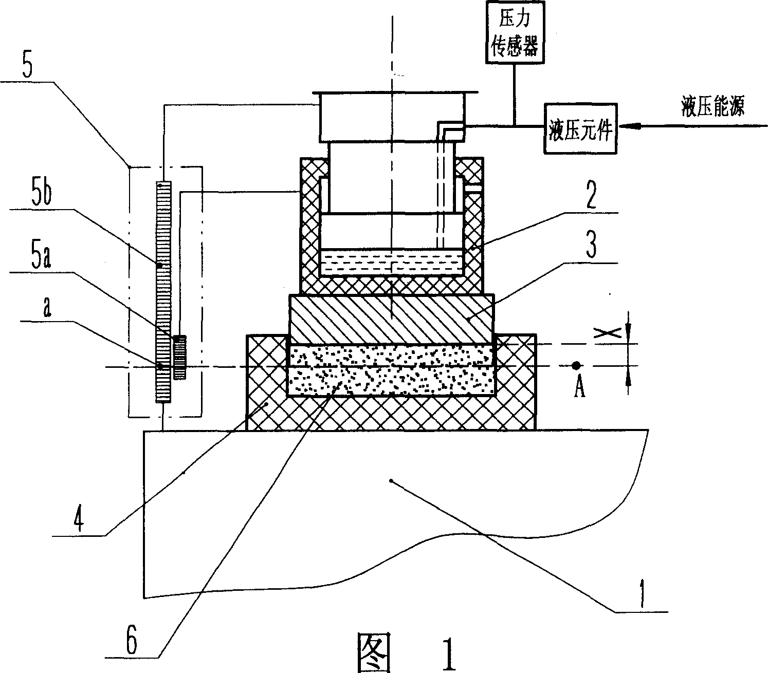
[0009] Fig. 1 is a working principle diagram of the present invention applied to a moving beam ceramic tile press. The moving beam ceramic tile press includes a workbench 1 fixed to a frame, and a moving beam 2 that can move up and down. The moving beam 2 is actually a piston cylinder that can move up and down. When hydraulic oil is injected into the cylinder, the moving beam 2 moves downward. The pressure of the downward movement of the moving beam 2 to press the powder is controlled by the closed-loop hydraulic control system. The upper and lower molds 3 and 4 are installed on the moving beam 2 and the workbench 1 respectively. In order to measure the relative displacement of the molds 3 and 4, a grating digital displacement sensor 5 is installed between the moving beam 2 and the workbench 1. The fixed grating ruler 5b in the sensor is fixed on the frame, and the moving grating ruler 5a follows the beam 2 exercise together. The ceramic powder 6 to be pressed is filled and...


PUM


Abstract

A pressure-type control method with shift monitor for the hydraulic forming machine using powder as raw material is disclosed. A shift sensor is used to monitor the relative shift between upper and lower moulds. The shift value is used as the feedback parameter of closed-loop hydraulic control system. When the relative shift value is correspondent with the predefined thickness variation of powder, it is determined that the powder has been pressed by a predefined pressure, so performing a closed-loop control.

Description

technical field [0001] The invention relates to a powder material hydraulic forming machine, in particular to a pressure control method of the powder material hydraulic forming machine. Background technique [0002] The main function of the powder hydroforming machine is to use a certain pressure to press the powder in the mold into a green body with a certain shape and strength. For example, the ceramic brick press used in the wall and floor tile production line uses a certain pressure to press the ceramic powder in the mold into a brick. In order to control the magnitude of the pressure, currently known powder hydraulic molding machines all use the pressure of the main cylinder monitored by the pressure sensor as the feedback parameter of the pressure closed-loop control. This pressure control mode has many disadvantages: 1. The pressure of the hydraulic oil circuit is disturbed and affected by many factors, and it is difficult to ensure the repeatability of each pressuri...

Claims


Application Information

Patent Timeline
IPC IPC(8): B30B11/00G05B11/60
Inventor 魏继荣黄卫华彭沪新陈保伟
Owner FOSHAN HENGLITAI MACHINERY
Why Eureka
Try Eureka