Combustion apparatus and combustion method

A combustion device and combustion chamber technology, applied in the direction of combustion methods, burners, combustion chambers, etc., can solve the problems of increased cost and complex structure, and achieve the effects of high stability, suppression of thermal NOx generation, and easy use

Inactive Publication Date: 2007-02-21
EBARA CORP
View PDF5 Cites 10 Cited by
  • Summary
  • Abstract
  • Description
  • Claims
  • Application Information

AI Technical Summary

Problems solved by technology

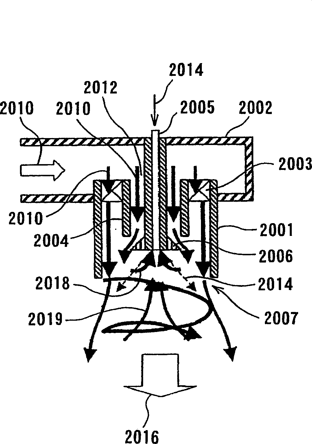
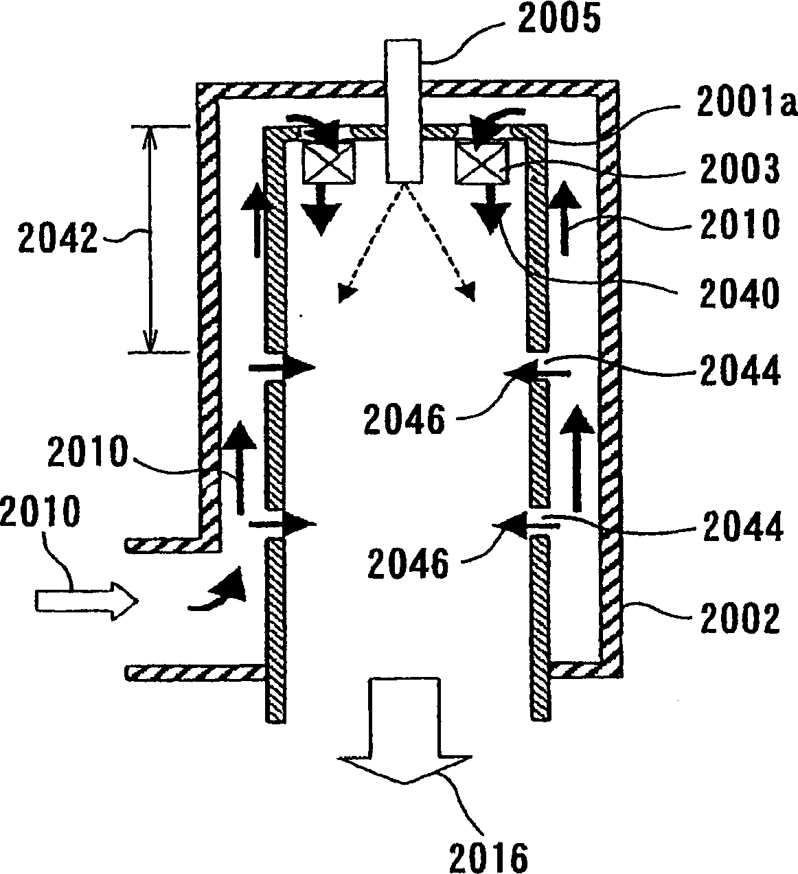
[0033] In addition, the fuel nozzle 2005 and the ignition device (not shown) need to pass through the inflow housing 2002a and be installed on the container 2001a, but due to the need to absorb thermal expansion and pass through the structure of the inflow housing 2002a, the structure is complicated and the cost increases

Method used


Image

  • Combustion apparatus and combustion method
  • Combustion apparatus and combustion method
  • Combustion apparatus and combustion method

Examples


Embodiment Construction

[0102] Below, refer to Figure 4 to Figure 36 , the combustion device according to the embodiment of the present invention will be described. In each embodiment, the same part is denoted by the same code|symbol, and repeated description is abbreviate|omitted.

[0103] First, refer to Figure 4 and Figure 5 , the combustion device in the first embodiment will be described. Figure 4 and Figure 5The combustion device shown is a general-purpose combustion device mainly applicable to boilers and industrial furnaces, or may also be applicable to gas turbines, and has a cylindrical container (hereinafter simply referred to as "container") with one end (closed end) 10 closed. 12. An inflow housing 14, a gyrator 16 and a fuel nozzle 18 disposed through the upper end (closed end) 10 of the aforementioned container 12. On the side surface 13 of the container 12, a plurality of air inflow parts 20 are formed at the same pitch, and the combustion air 22 is formed to flow into the c...


PUM


Abstract

A combustion apparatus according to the present invention can positively control and generate burnt gas recirculation with a simple structure. The combustion apparatus has a cylindrical container (12) having a combustion chamber, a close end (10), and an open end (26), an inflow passages (20) for supplying combustion air into the combustion chamber in the cylindrical container (12), and a fuel nozzle (18) for supplying fuel into the combustion chamber in the cylindrical container (12). A flow (28) of air is formed so as to have a velocity component in a direction of a central axis (J) from the open end (26) to the close end (10) and a velocity component to swirl in a circumferential direction of said annular container (12). Fuel (23) is injected so as to have a velocity component in the direction of the central axis (J) from the close end (10) to the open end (26) and a velocity component directed radially outward.

Description

technical field [0001] The present invention relates to a combustion device and a combustion method, and in particular, to a combustion device and a combustion method that allow combustion air and fuel to flow into a combustion chamber, and perform combustion by mixing the combustion air and fuel. Background technique [0002] Regulations on air pollutants discharged from combustion devices, especially nitrogen oxides (NOx) have been increasingly tightened, and reductions in NOx emissions have been sought. [0003] Nitrogen oxides (NOx) are roughly classified into three types, thermal NOx, prompt NOx, and combustion NOx, according to their generation mechanism. Thermal NOx is strongly dependent on temperature because it is produced by the reaction of nitrogen and oxygen in the air at high temperature. Prompt NOx is formed especially in fuel-rich flame belts. Combustion NOx is generated in association with nitrogen compounds contained in fuel. [0004] Recently, clean fuel...

Claims


Application Information

Patent Timeline
Patent Type & Authority Applications(China)
IPC IPC(8): F23D11/12F23D14/02F23D21/00F23L1/00F23R3/10F23C6/04F23C7/00F23C99/00F23D11/00F23D11/40F23D14/22F23D17/00F23D99/00F23R3/14
CPCF23C6/045F23C2900/06041F23C7/002F23D17/002F23D11/404
Inventor 天野俊辅新井雅隆
Owner EBARA CORP
Why Eureka
Try Eureka