Filter element for dust collector

A technology of vacuum cleaners and filter elements, which is applied in the direction of suction filters, etc., and can solve problems such as affecting air permeability and difficulty in cleaning foreign substances such as dust

Inactive Publication Date: 2007-02-28
LG ELECTRONICS (TIANJIN) APPLIANCES CO LTD
View PDF0 Cites 23 Cited by
  • Summary
  • Abstract
  • Description
  • Claims
  • Application Information

AI Technical Summary

Problems solved by technology

[0010] The purpose of the present invention is to solve the problem in the prior art that it is difficult to clean the dust and other foreign substances embedded in the folds of the filter

Method used


Image

  • Filter element for dust collector
  • Filter element for dust collector
  • Filter element for dust collector

Examples


Embodiment Construction

[0031] The present invention will be described in detail below in conjunction with the accompanying drawings and embodiments.

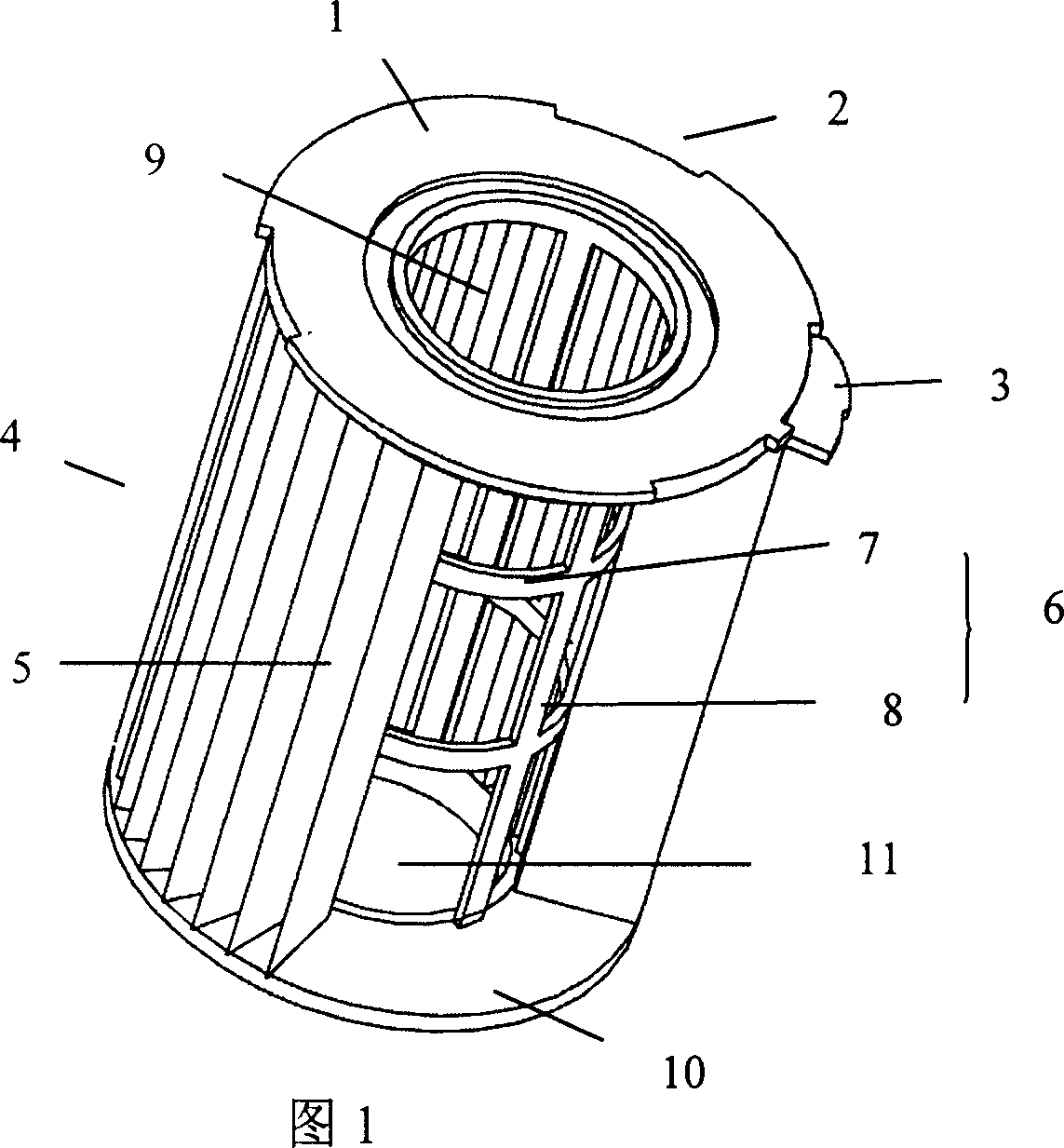
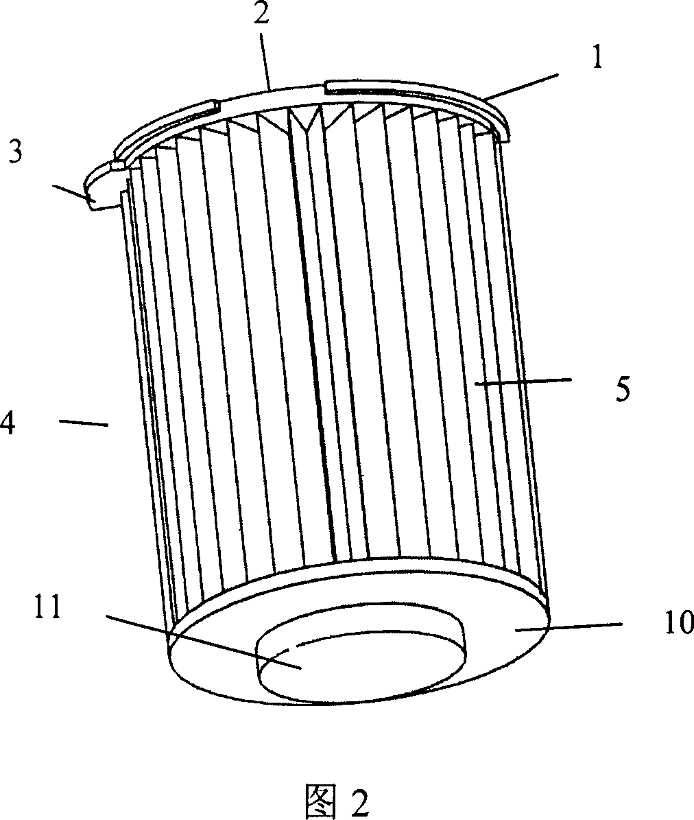
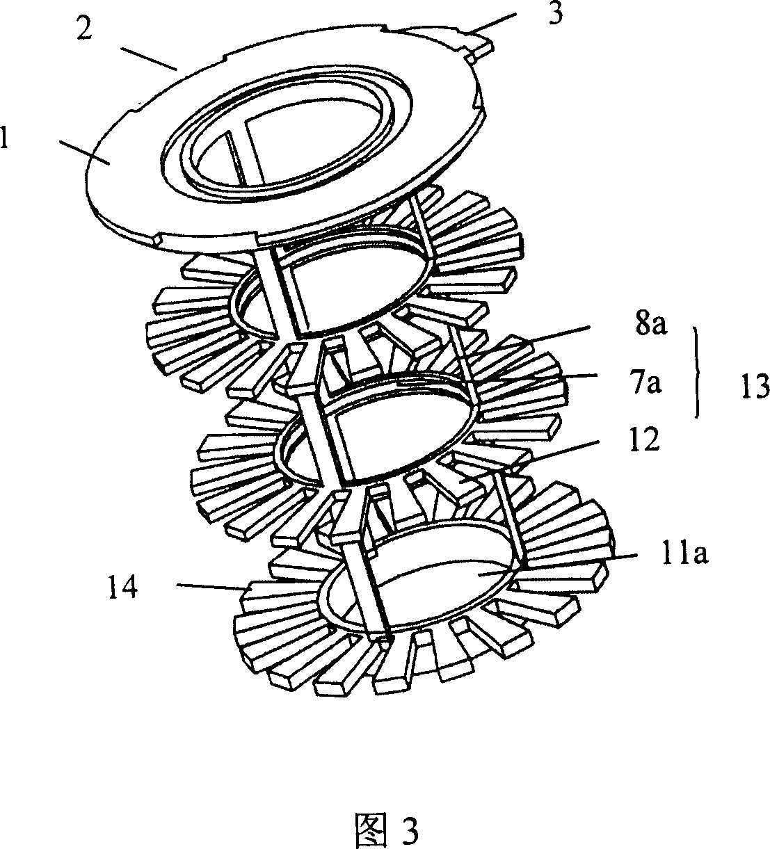
[0032] A vacuum cleaner filter element, comprising a concentric upper bracket 1 with a central hole at both ends of the filter element and a base frame plate 14 with a bottom groove 11a, and a hoop 7a is arranged between the upper bracket 1 and the base frame plate 14 The hollow frame 13 integrated with the support rod 8a is fixed to the periphery of the hollow frame 13 between the bottom surface of the upper bracket 1 (not shown) and the circular base, and is fixed to a cylindrical shape with folds of equal amplitude. The filter paper tube 4a; the folds that are continuously folded back on the cylindrical filter paper tube 4a are trapezoidal folds 15 with the top edge inward and the bottom edge outward; the base with the bottom groove 11a forms the top edge inward and the bottom edge outward The outer base frame plate 14; the outer periphery of the h...


PUM


Abstract

The invention discloses a filter core structure of cleaner, which comprises the following parts: upper rack with concentric round central hole and bottom flute chassis on two ends of filter core, hollow frame with hoop and rod between upper rack and chassis, hollow rack periphery between rack bottom loop groove and round chassis, cylinder-shaped filter paper cylinder with continuous folding equal-wave fold, wherein the fold displays trapezoid, the chassis forms trapezoidal rack, the trapezoidal rack is also formed on the periphery of hollow frame of rod.

Description

technical field [0001] The invention relates to a filter device of a vacuum cleaner, in particular to a filter element of a vacuum cleaner. Background technique [0002] Vacuum suction is a cleaning and sanitary appliance used to remove dust from floors, carpets, walls, furniture, clothing and various gaps. [0003] Vacuum cleaners generally include a vacuum cleaner motor that generates suction from an imported power supply, a motor inlet that forms an air path system, a suction nozzle, a hose, and a dust collection device that collects inhaled matter. [0004] According to the shape of vacuum cleaners, they can be divided into upright vacuum cleaners, horizontal vacuum cleaners and portable vacuum cleaners. [0005] Generally speaking, a horizontal vacuum cleaner includes an upper cover and a bottom case. The upper cover is equipped with a vacuum hose connection device, the rear of the bottom shell is equipped with a horizontal reel and a dust collector for collecting inh...

Claims


Application Information

Patent Timeline
IPC IPC(8): A47L9/12
Inventor 杨健涛
Owner LG ELECTRONICS (TIANJIN) APPLIANCES CO LTD
Why Eureka
Try Eureka