Motor-driven wheel drive device

A wheel-driven, electric technology, applied in electromechanical devices, electric vehicles, electric devices, etc., can solve the problems of setting space constraints and space increase, and achieve the effects of improving the degree of freedom, reducing braking torque, and reducing costs

Inactive Publication Date: 2007-02-28
NTN CORP
View PDF1 Cites 61 Cited by
  • Summary
  • Abstract
  • Description
  • Claims
  • Application Information

AI Technical Summary

Problems solved by technology

[0011] In such a conventional electric wheel drive device 51, such a gear reducer 55 can be easily assembled with various components, but on the contrary, since the electric motor 54 arranged inside the wheel 53 is miniaturized

Method used


Image

  • Motor-driven wheel drive device
  • Motor-driven wheel drive device
  • Motor-driven wheel drive device

Examples


Embodiment 1

[0112] Embodiments of the present invention will be described in detail below based on the drawings.

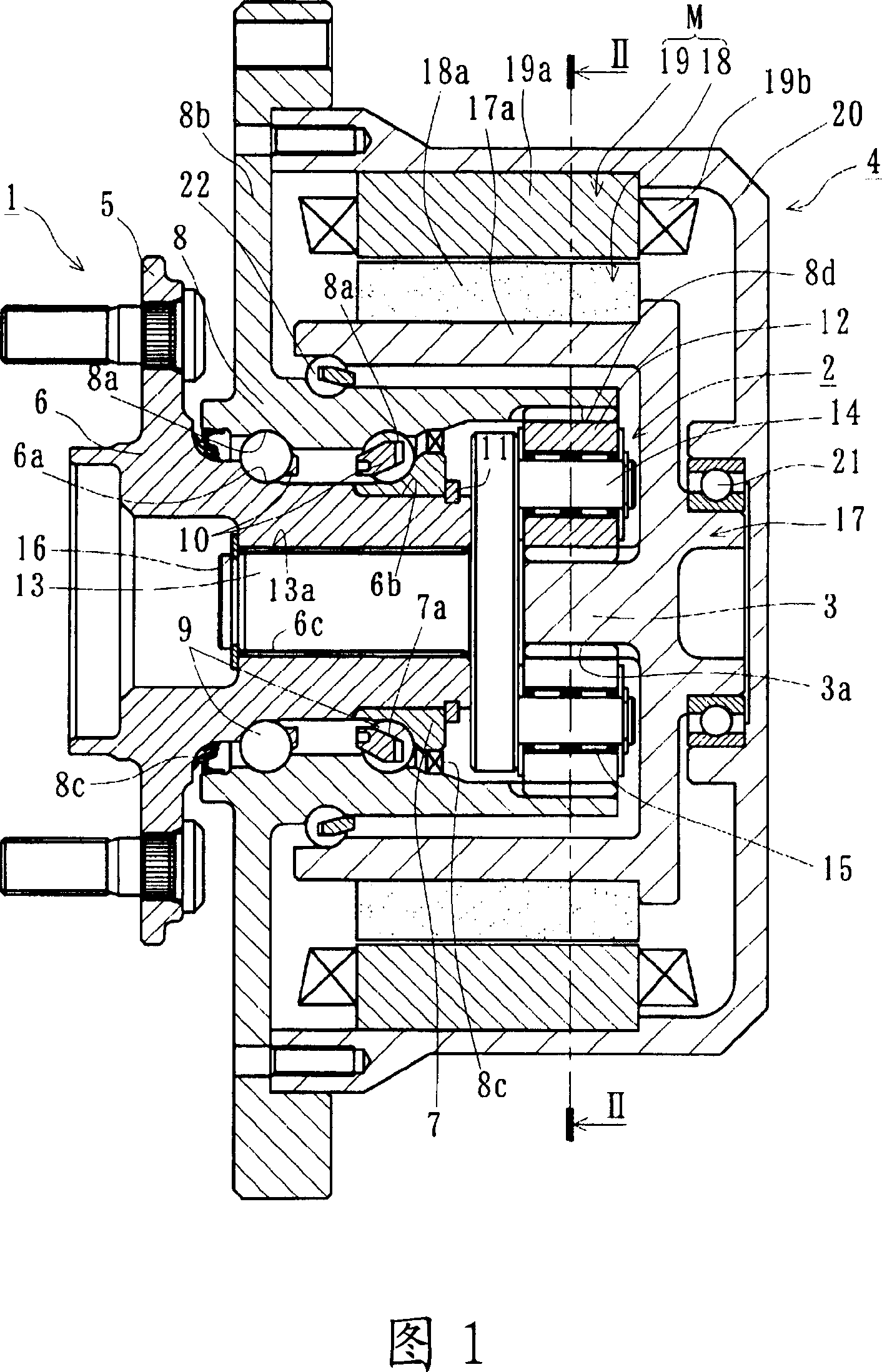
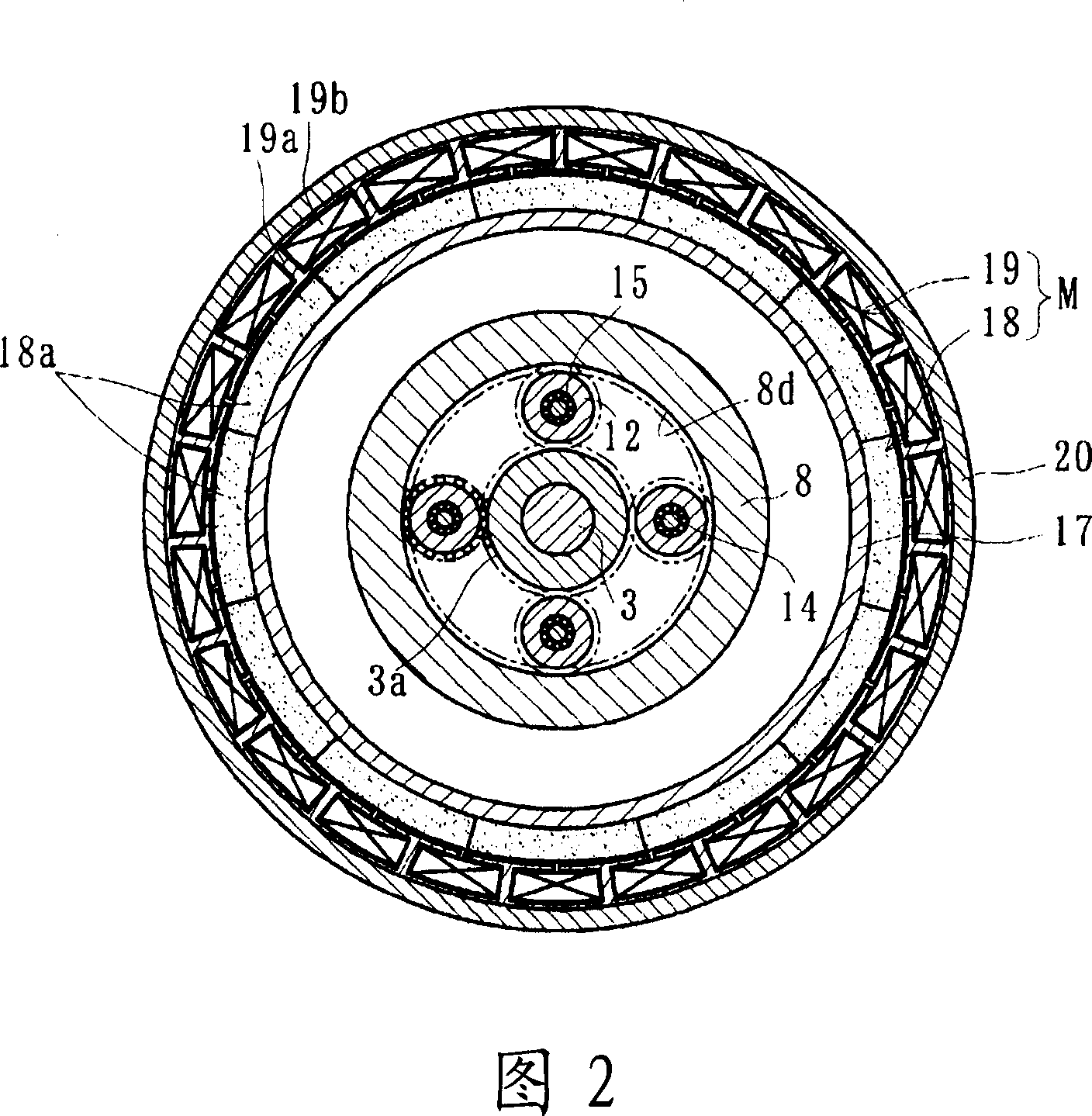
[0113] 1 is a longitudinal sectional view showing a first embodiment of an electric wheel drive device according to the present invention, and FIG. 2 is a transverse sectional view taken along line II-II in FIG. 1 .

[0114] The electric wheel driving device mainly includes: a wheel bearing 1; a planetary speed reducer 2 mounted on the wheel bearing 1; and a driving part 4 integrally provided with a sun gear 3, and the sun gear 3 constitutes the planetary speed reducer 2. In addition, in the following description, in the assembled state of the vehicle, the side closer to the outer side of the vehicle is referred to as the outer side (left side in the drawing), and the side closer to the center is called the inner side (right side in the drawing).

[0115]The wheel bearing 1 is called the third generation for supporting a driving side wheel (not shown). This wheel bearing 1 ...

Embodiment 2

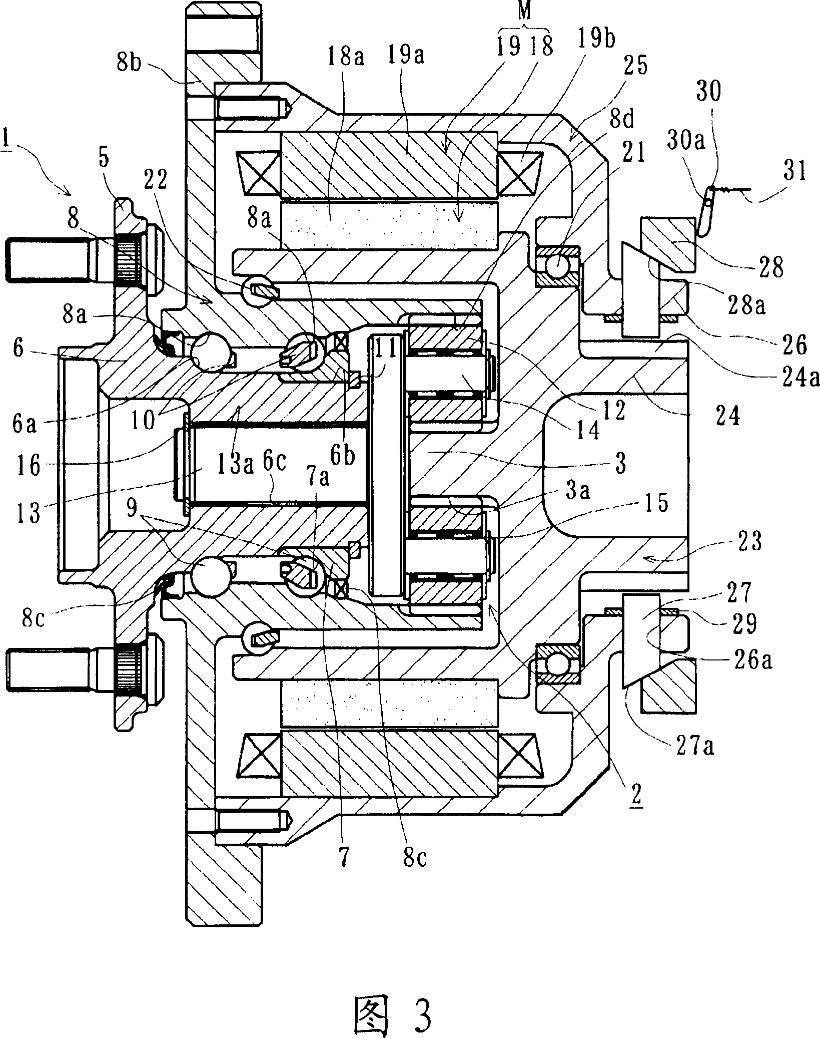
[0124] FIG. 3 is a longitudinal sectional view showing a second embodiment of the electric wheel drive device of the present invention, and FIG. 4 is a perspective view of main parts of FIG. 3 . In addition, since this second embodiment differs from the above-mentioned first embodiment (FIG. 1) only in the structure of the drive unit, the same reference numerals are assigned to other identical components, identical parts, or parts having the same functions, and detailed description thereof will be omitted. .

[0125] A cylindrical portion 24 extending inward is protruded from the rotating member 23 , and a plurality of concave portions 24 a are formed at equal intervals in the circumferential direction on the outer periphery of the cylindrical portion 24 . In addition, a cylindrical portion 26 facing the cylindrical portion 24 protrudes from the inner side of the stator case 25, and a plurality of through holes 26a are formed corresponding to the recessed portion 24a. The int...

Embodiment 3

[0130] Fig. 5 is a longitudinal sectional view showing a third embodiment of the electric wheel drive device of the present invention. In addition, since this third embodiment differs from the above-mentioned second embodiment ( FIG. 3 ) only in the structure of the brake portion, the same reference numerals are assigned to other identical components, identical parts, or parts having the same functions, and details thereof are omitted. illustrate.

[0131] A cylindrical portion 33 extending inward protrudes from the rotating member 32 , and a tapered surface 33 a is formed on the inner periphery of the cylindrical portion 33 . On the other hand, an annular intermediate member 34 is disposed so as to face the rotating member 32 in the axial direction, and a tapered surface 34 a corresponding to the above-mentioned tapered surface 33 a is formed on the outer periphery of the intermediate member 34 . In addition, a concave portion 35 is formed on the inner side surface of the ro...


PUM

PropertyMeasurementUnit
Surface hardnessaaaaaaaaaa

Abstract

The invention provides a motor-driven wheel drive device in which the durability of a wheel bearing is increased, the weight and size thereof are reduced, and the disassembly and reassembly thereof is taken into account. [MEANS FOR SOLVING PROBLEMS] This motor-driven wheel drive device comprises a drive part (4) having an electric motor (M) driving a planetary speed reduction gear (2) installed in the wheel bearing (1) and a rotating member (17). The wheel bearing (1) further comprises a hub wheel (6) on which an inside rolling surface (6a) is formed, an inner ring (7) press-fitted to the hub wheel, an outer member (8) in which double rows of outside rolling surfaces (8a) are formed, and rolling elements (9). The planetary speed reduction gear (2) further comprises a sun gear (3) formed in a rotating member (17), a plurality of planetary gears (12) disposed between the outer member (8) and the sun gear (3), and carrier pins (14) pivotally supporting these planetary gears on a connection shaft (13). The drive part (4) further comprises the electric motor (M) releasably disposed on the outer member (8) and the rotating member (17). The connection shaft (13) is connected to the hub wheel (6) through a serration, and the rotation of the electric motor (M) is transmitted to the hub wheel (6) through the rotating member (17) and the planetary speed reduction gear (2).

Description

technical field [0001] The present invention relates to an electric wheel driving device, which is used for vehicles such as electric vehicles, golf carts or forklifts, and the wheel bearing and the motor are integrated. Background technique [0002] In order to improve the driving efficiency when the wheels are driven by electric motors, electric wheel drive devices have been proposed which are used for driving wheels of vehicles such as electric vehicles and are configured to directly drive the wheels by electric motors. However, in such an electric wheel drive device, since the electric motor requires a large output torque, a large electric motor has to be used. This not only increases the cost but also increases the weight, making it difficult to sufficiently ensure the running performance of the vehicle. [0003] In view of this, a kind of electric wheel driving device (wheel motor) with speed reducer has also been proposed, which is equipped with electric motor and pl...

Claims


Application Information

Patent Timeline
IPC IPC(8): B60K7/00B60K17/04B60T1/06F16D63/00F16D65/02F16D65/18F16H37/04H02K7/102H02K7/116H02K7/14H02K21/14
CPCB60K2007/0092H02K7/102H02K7/14B60K2007/0038B60K7/0007B60K17/046H02K7/116F16C41/004F16C19/186F16C2326/02B60L2220/44F16C2380/27Y02T10/64
Inventor 斋藤刚岩本宪市
Owner NTN CORP
Why Eureka
Try Eureka