Optical device and optical pickup device

一种光学器件、受光元件的技术,应用在光学探测器、光束引导装置、光学记录头等方向,能够解决误差信号偏差、构造复杂、制造困难等问题,达到防止信号调制度的恶化及误差信号的偏差、易于确保、易于小型化的效果

Inactive Publication Date: 2007-02-28
VICTOR CO OF JAPAN LTD
View PDF1 Cites 0 Cited by
  • Summary
  • Abstract
  • Description
  • Claims
  • Application Information

AI Technical Summary

Problems solved by technology

However, when the area of ​​the light-receiving region is enlarged, the amount of receiving the above-mentioned unnecessary reflected light increases approximately in proportion to the enlargement of the area. dynamic range of
[0016] Here, in order to avoid this problem, it is considered to separate the light-receiving area for each wavelength. However, only by separating the light-receiving area, although the unnecessary light component can be halved, there is a problem that it cannot be completely removed.
[0017] In addition, for example, in an optical pickup device provided with a light-receiving part for canceling offset as described in Japanese Patent Application Laid-Open No. 11-73658, it is necessary to increase the area of ​​the hologram element only for so-called offset canceling. Divide and light-receiving area and use dedicated calculation circuit, so there is a problem of cost increase due to complicated structure and difficult manufacturing

Method used


Image

  • Optical device and optical pickup device
  • Optical device and optical pickup device
  • Optical device and optical pickup device

Examples


Embodiment Construction

[0066] Embodiments of the optical device and the optical pickup device of the present invention will be described in detail below with reference to the drawings.

[0067] Next, first, the configuration of the optical pickup device will be described.

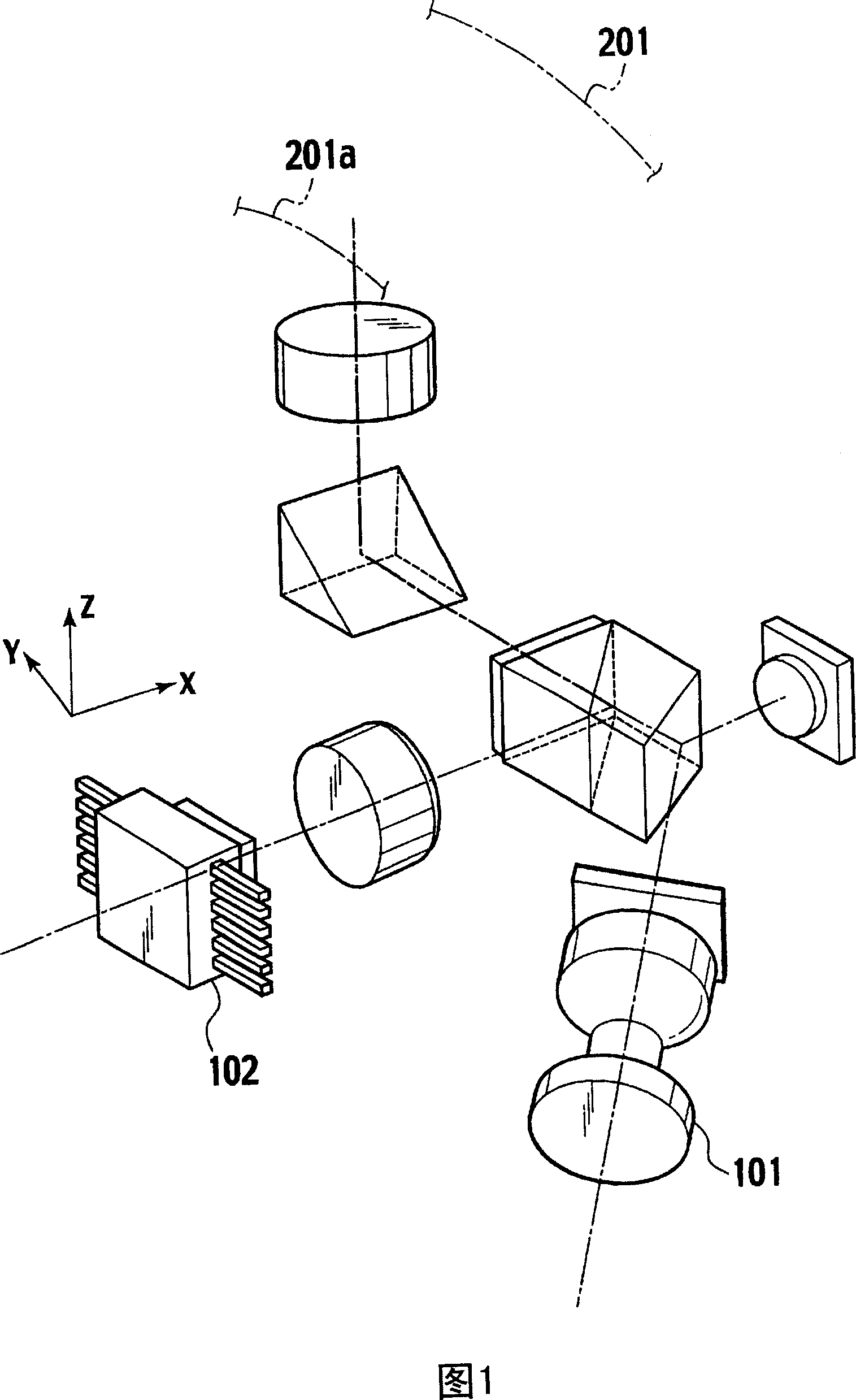
[0068] Fig. 4 is a perspective view showing the structure of the optical pickup device of the present invention.

[0069] As shown in FIG. 4 , the optical pickup device has a first laser light source 1 that emits laser light with a first wavelength (for example, 650nm frequency band). The laser light of the first wavelength emitted from the first laser light source 1 passes through the collimator lens 2 to become a parallel beam, and is divided into three beams of 0-order light and ±1-order light by the first grating 3, and then enters the Beam splitting prism 4 with beam shaping function. The 0th-order beams of the first grating 3 serve as main beams for recording and reproducing information signals from the optical disc, and ...


PUM


Abstract

There is provided an optical device for receiving an incident light on the light reception surfaces (20A-29) on the light reception element by diffracting the incident light by a hologram element. The optical device receives a reflection light of sub beam used for tracking operation on the different light reception surfaces depending on the wavelength. When an incident light of one wavelength is received on one light reception surface (22, 23, 26, 27), calculation is performed according to the output signal from the one light reception surface and the output signal from other light reception surface (24, 25, 28, 29) so as to detect an unnecessary light component. Thus, when recording and / or reproducing an information signal onto / from an optical disc using a light source of a different wavelength such as 'DVD' and 'CD', it is possible to eliminate the affect by an unnecessary reflection light from the optical disc and eliminate calculation complexity about the output signal.

Description

technical field [0001] The present invention relates to an optical device of an optical pickup device used for recording and reproducing an information recording medium such as an optical disk, and to an optical pickup device constructed using such an optical device. Background technique [0002] Conventionally, various optical discs have been proposed as information recording media. As such an optical disc, a "DVD" (Digital Versatile Disc) standard optical disc having about seven times the recording capacity of a "CD" (compact disc) standard optical disc has rapidly spread in recent years. "DVD-Video" in which video signals are recorded on this "DVD" can be reproduced in large quantities, and will replace videotape media such as "VHS" (trade name) as a medium for distribution and rental of contents such as movies. [0003] In addition, the so-called "DVD-RAM", "DVD-R", "DVD-RW", "+R", "+RW" and other optical disc standards that users can record information signals are also...

Claims


Application Information

Patent Timeline
Patent Type & Authority Applications(China)
IPC IPC(8): G11B7/135G11B7/09G11B7/13G11B7/00G11B7/005G11B7/125G11B7/1275G11B7/131G11B7/1353
CPCG11B7/094G11B7/0943G11B2007/0013G11B7/131G11B2007/0006G11B7/005G11B7/1275G11B7/1353G11B7/09
Inventor 大山实
Owner VICTOR CO OF JAPAN LTD
Why Eureka
Try Eureka