
Method of controlling temperature

A temperature control method and average temperature technology, applied in temperature control, electric temperature control, self-adaptive control, etc., can solve problems such as inability to propose solutions, inability to provide system fan collocation suggestions, and low cost

Inactive Publication Date: 2007-03-07
INVENTEC CORP
View PDF0 Cites 13 Cited by
  • Summary
  • Abstract
  • Description
  • Claims
  • Application Information

AI Technical Summary

Problems solved by technology

[0006] Although the above-mentioned heat dissipation methods can reduce the temperature inside the computer case, they cannot provide proper system fan matching suggestions, especially when users or business users want to control the temperature inside the computer case, how many systems should be installed? Only the fan can cope with the temperature of the computer and how to configure the position of the system fan to obtain the system fan configuration with the lowest cost and the best cooling effect. As far as the existing technology is concerned, it is really impossible to propose an effective solution

Method used


Image

  • Method of controlling temperature
  • Method of controlling temperature
  • Method of controlling temperature

Examples


Embodiment Construction

[0043] In order to have a further understanding of the purpose, structural features and functions of the present invention, the detailed description is as follows in conjunction with relevant embodiments and accompanying drawings.

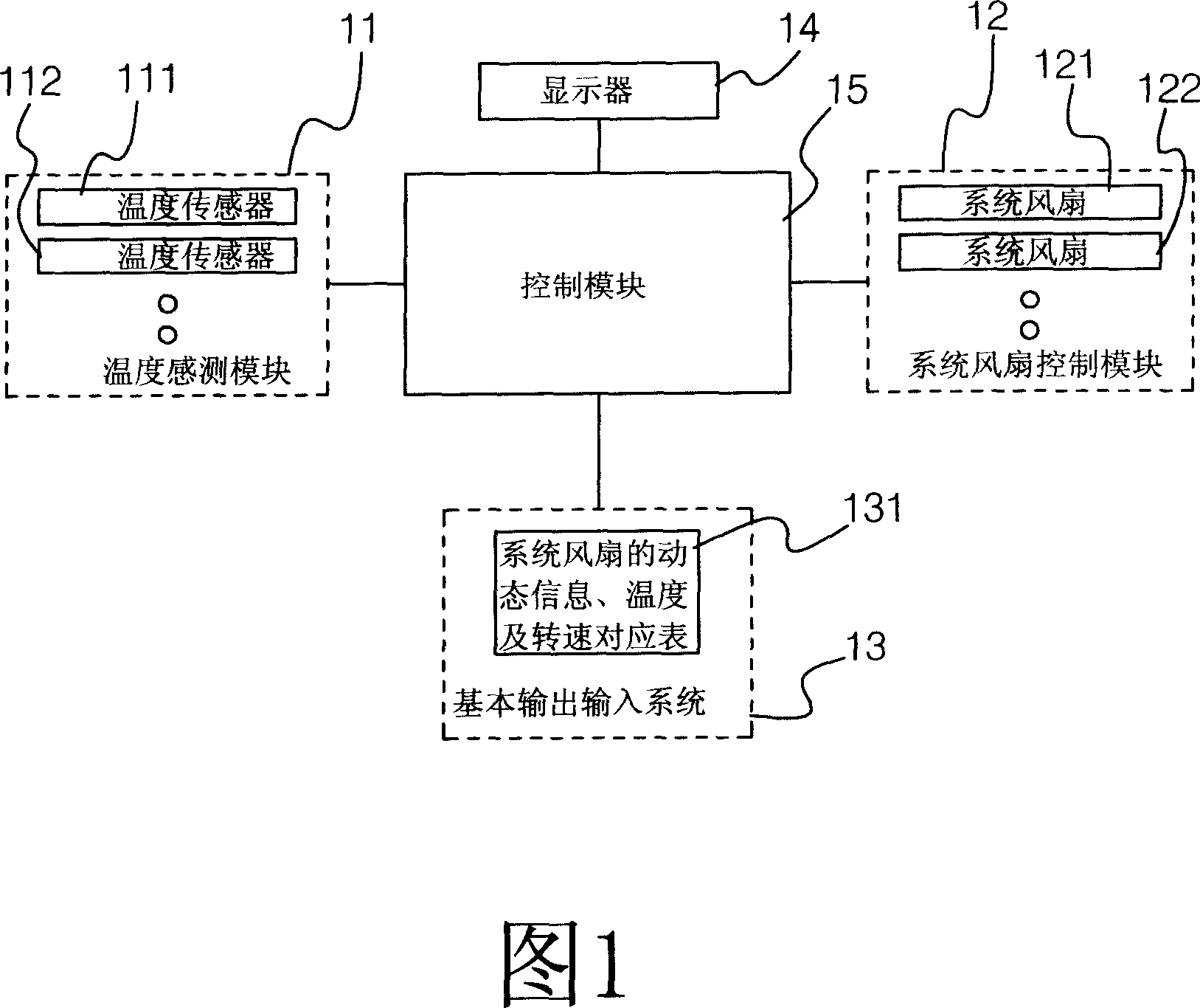
[0044] As shown in Figure 1, it is a block diagram of the temperature control system of the present invention, the temperature control system 1 of the present invention includes a temperature sensing module 11, a system fan control module 12, a basic input and output system 13, a display 14 and a control Module 15.

[0045] The temperature sensing module 11 includes more than one temperature sensor 111 , 112 , which are placed around the casing respectively for sensing the temperature inside the casing. The system fan control module 12 includes more than one system fan 121, 122, which are respectively placed in different installation positions in the casing, except for sucking cold air from the outside of the casing or exhausting hot air from the o...


PUM


Abstract

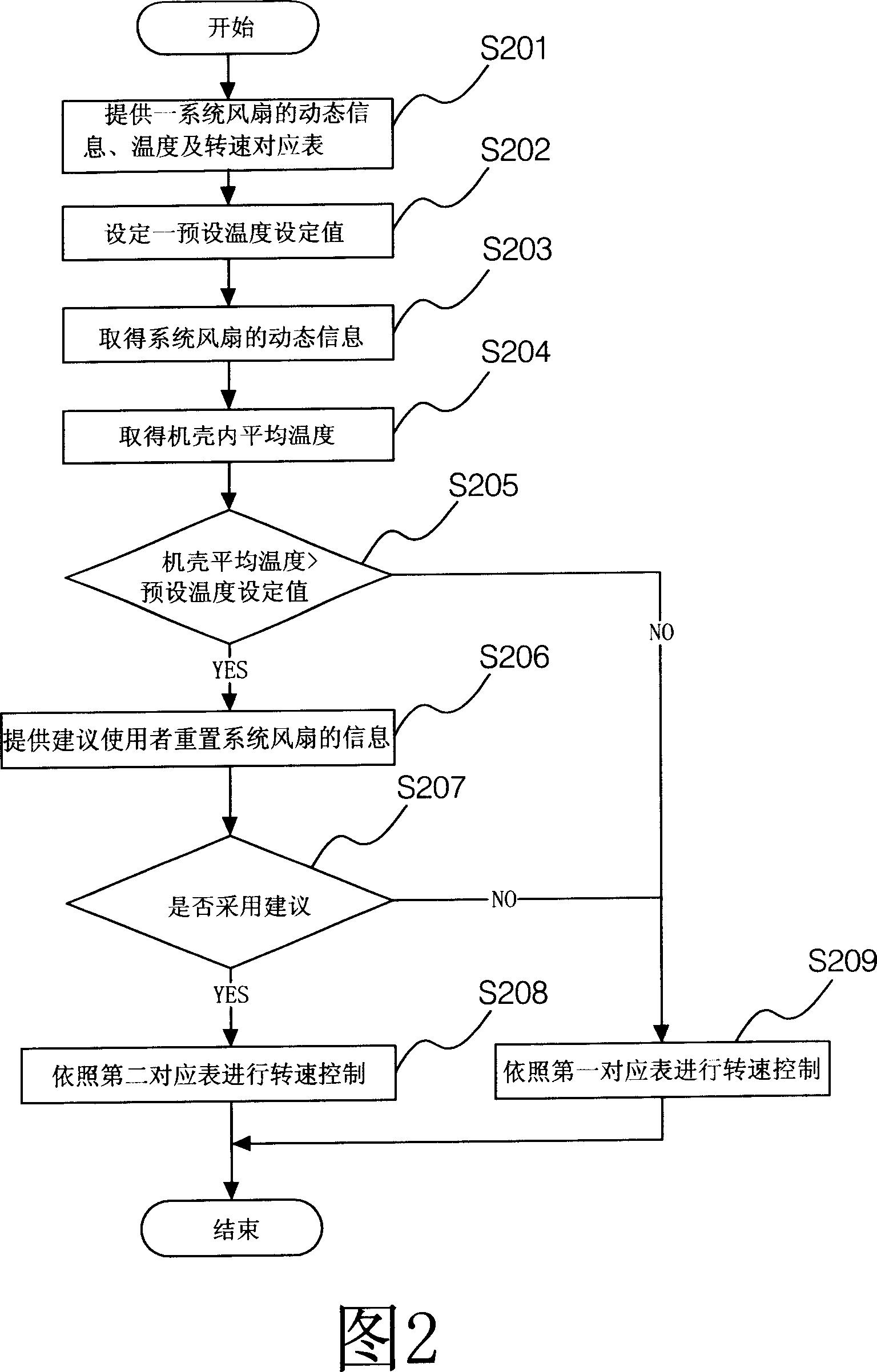
This invention discloses one temperature control method, which comprises the following steps: providing one system fan dynamic information, temperature and rotation list; getting system fan dynamic information and computer shell inner temperature to control more than one system fun rotation speed; when shell even temperature value is larger than pre-set one, then control system tells user re-match system fan and then when user takes and starts system fan; when user doesn't take, not re-match system fan to process dissipation according to the comparison list.

Description

technical field [0001] The invention relates to a temperature control method, in particular to a temperature control method applied to a computer casing. Background technique [0002] Whether general users or business users buy computers, they often think that the selection of the case only needs to be installed with a motherboard, power supply, hard disk, graphics card, and optical drive due to limited budget. In fact, whether a computer can operate stably depends on the case, because the above-mentioned parts are all stuffed in the case, and these parts are all electronic products, so when the computer is in normal operation, Every electronic component inside an enclosure must generate heat. If users or enterprise users are for certain purposes, such as CAD, mechanical drawing and other environments with high-speed computing, they must stuff a central processing unit with high-speed computing, a hard disk with 10,000 revolutions in the casing, or in order to achieve 3D g...

Claims


Application Information

Patent Timeline
IPC IPC(8): G05D23/00G05D23/19G05B19/04G05B13/00G05B15/02G06F17/00
Inventor 杨子毅
Owner INVENTEC CORP
Learn More