
Optical detection device and detection method

An optical detection and optical lens technology, which is applied to measurement devices, material analysis by optical means, scientific instruments, etc., can solve the problems such as the penetrating pattern test board 21 does not provide Moiré patterns, and the test speed is slow, so as to achieve accelerated The effect of improving test speed and accuracy

Inactive Publication Date: 2009-08-19
HONG FU JIN PRECISION IND (SHENZHEN) CO LTD +1
View PDF4 Cites 0 Cited by
  • Summary
  • Abstract
  • Description
  • Claims
  • Application Information

AI Technical Summary

Problems solved by technology

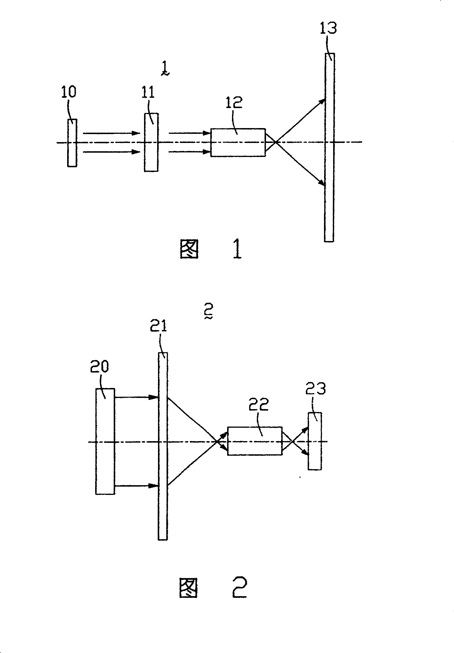
[0008] Equally, this optical detection device 2 does not provide the moiré pattern because the penetrating pattern testing board 21, so if the data such as the degree of distortion and chromaticity of this optical lens module 22 are to be detected, the penetrating pattern must be replaced. Pattern test board 21, or reset the test environment
resulting in slower tests

Method used


Image

  • Optical detection device and detection method
  • Optical detection device and detection method
  • Optical detection device and detection method

Examples


Embodiment Construction

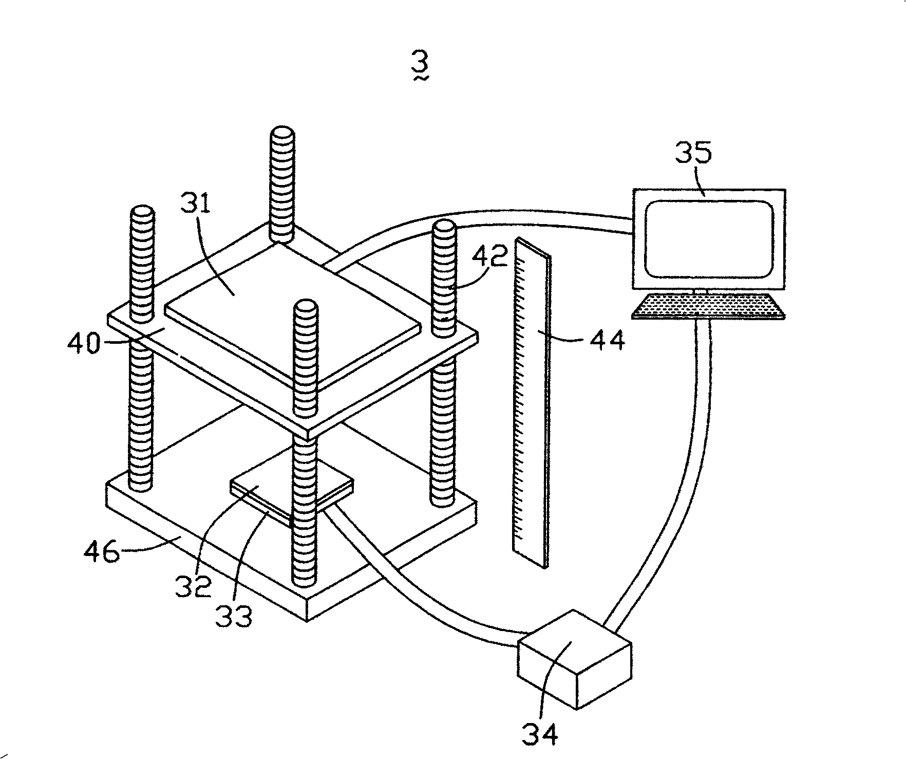
[0028] see image 3 , is a schematic structural view of the optical detection device of the present invention. The optical detection device 3 mainly includes a flat panel display 31 , an image sensor 33 , a computer system 35 and a signal transition box 34 connecting the computer system 35 and the image sensor 33 .

[0029] The flat panel display 31 is set on a transparent upper support platform 40 , and the display surface faces the image sensor 33 . The flat panel display 31 has relatively high resolution, and the average dot pitch is between 0.2-0.3mm.

[0030] The image sensor 33 is located on a lower support platform 46 arranged parallel to the upper support platform 40, the image sensor 33 is connected with the computer system 35 through a signal transfer box 34, and the captured image data can be transmitted to the computer system 35.

[0031] The upper support platform 40 is connected with the lower support platform 46 by four pillars 42, and the pillars 42 are perp...


PUM


Abstract

The invention relates to an optical detection device and a detection method for an optical lens module. The optical detection device includes a flat-panel display, an image sensor and a computer system that controls the flat-panel display to display different test patterns, the computer system is connected to the image sensor, and the optical lens module to be tested is located between the flat-panel display and the image sensor. Meanwhile, the test pattern displayed on the flat-panel display is imaged on the image sensor via the optical lens module to obtain image data corresponding to the different test patterns, and the image data is input into the computer system. The optical detection device and detection method of the present invention use a computer system to control a flat display to display different test patterns, which can make the detection process faster.

Description

technical field [0001] The invention relates to an optical detection device and a detection method, in particular to an optical detection device and a detection method for detecting an optical lens. Background technique [0002] In digital imaging products, the optical module is usually an indispensable component, and the quality of the optical lens in the optical module directly affects the display quality of the optical module and even the digital imaging product. [0003] A kind of optical detection device of prior art optical lens resolution (Resolution) such as figure 1 shown. The optical detection device 1 mainly includes a parallel light source 10 , a penetrating pattern test plate 11 and a linear charge coupled device (Charge Coupled Device, CCD) 13 . [0004] During detection, the optical lens module 12 is arranged between the penetrating pattern test plate 11 and the linear CCD 13, and the parallel light beam emitted by the parallel light source 10 passes through...

Claims


Application Information

Patent Timeline
Patent Type & Authority Patents(China)
IPC IPC(8): G01N21/958G01N21/84
Inventor 张仁淙
Owner HONG FU JIN PRECISION IND (SHENZHEN) CO LTD
Learn More