Hydraulic equipment for hot-rolled member scale removal

A descaling equipment and equipment technology, applied in the direction of workpiece surface treatment equipment, metal processing equipment, metal rolling, etc., can solve the problems of insufficient descaling, no descaling, etc.

Active Publication Date: 2007-03-07
HERMETIK HYDRAULIK
View PDF1 Cites 17 Cited by
  • Summary
  • Abstract
  • Description
  • Claims
  • Application Information

AI Technical Summary

Problems solved by technology

Therefore, when the row of nozzle heads is transverse to the direction of movement of the rolling stock, there may be streaks of insufficient or no descaling on the surface between adjacent nozzle heads

Method used


Image

  • Hydraulic equipment for hot-rolled member scale removal
  • Hydraulic equipment for hot-rolled member scale removal
  • Hydraulic equipment for hot-rolled member scale removal

Examples


Embodiment Construction

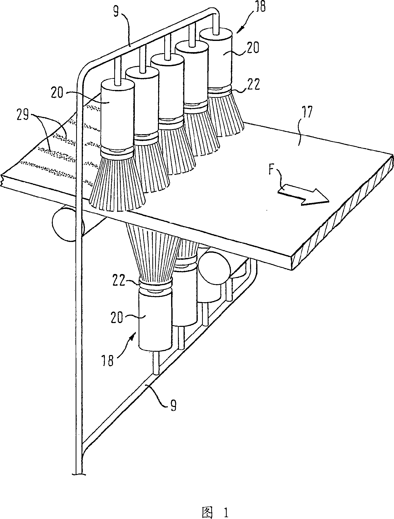
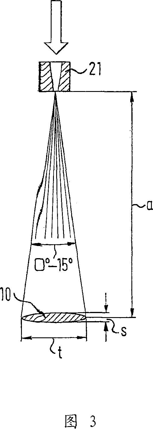
[0017] The rolling stock descaling plant shown in FIG. 1 comprises two rows 18 each comprising five stationary nozzle heads 20 and extending transversely in the direction of movement F on each side of the rolling stock 17 . Figure 2 shows one of the nozzle heads in detail. At its periphery, each nozzle head 20 is provided with four flat-bottomed nozzles 21 arranged on its periphery and mounted on a ring 22 of this nozzle head 20, which ring 22 is adapted to be driven in rotation. The nozzle is supplied with pressurized water via pipe 9 at a pressure of 300 to 1000 bar.

[0018] The ring 22 is driven at a rotational speed of 200 to 1000 r.p.m.

[0019] The nozzle head 20 is arranged so that the surface of the workpiece is at a distance a from the nozzle 21 and the workpiece moves in the direction of the arrow F below the stationary row of nozzle heads. As shown in FIG. 3 , this distance is chosen so that the length t of the major major axis and the length s of the minor major...


PUM


Abstract

The invention relates to a device which is used to descale warm rolling products (17) which can be displaced in relation to the device by high pressure water projection. Said device comprises at least one row of nozzle heads which cover the width of the rolling products, said row of nozzle heads comprising several nozzle heads (20). Each nozzle head is driven in a rotational manner by a motor about a rotational axis (A) which is essentially perpendicular to the surface to the rolling products and comprises at least two nozzles (1 8) which are disposed in an eccentric manner in relation to the rotational axis. The invention is characterised in that the nozzles (1 -8) of each nozzle head (20) are arranged as close as constructively possible on the periphery (25) of the nozzle head in such a manner that the nozzle head produces an injection image on the surface of the rolling product, said injection image at least touching the injection image of the nozzle head which is next in the row of nozzle heads.

Description

technical field [0001] The invention relates to equipment for descaling hot-rolled pieces, the strips move relative to the equipment and are sprayed by high-pressure water, the equipment includes at least one row of nozzle heads, the at least one row of nozzle heads swings in the width direction of the rolled piece and has A plurality of nozzle heads, each driven by a motor, rotate about an axis of rotation substantially perpendicular to the surface of the rolling stock, and include at least two nozzles disposed centrifugally with respect to the axis of rotation. Background technique [0002] In order to treat the surface of the rolled stock uniformly with devices of the type DE 43 28 303, the nozzles in each nozzle head are arranged at different angles relative to the axis of rotation so that the spray pattern of each nozzle covers a different radial area. It is therefore envisaged that the surface of the rolled stock treated with the nozzle head is also descaled uniformly...

Claims


Application Information

Patent Timeline
Patent Type & Authority Applications(China)
IPC IPC(8): B21B45/08
CPCB21B45/08Y10T29/4544B05B1/14B05B7/0892B05B13/0484
Inventor 于尔根·盖道尔
Owner HERMETIK HYDRAULIK
Why Eureka
Try Eureka