Damper rail
A track and body technology, applied in the field of track, can solve the problems of limited effective working area of damping material, limited effect of vibration and noise reduction, and track can not achieve the effect of vibration and noise reduction, achieve good effect of vibration and noise reduction, lighten rail And wheel wear, increase the effect of the effective contact area
- Summary
- Abstract
- Description
- Claims
- Application Information
AI Technical Summary
Problems solved by technology
Method used
Image
Examples
Embodiment 1
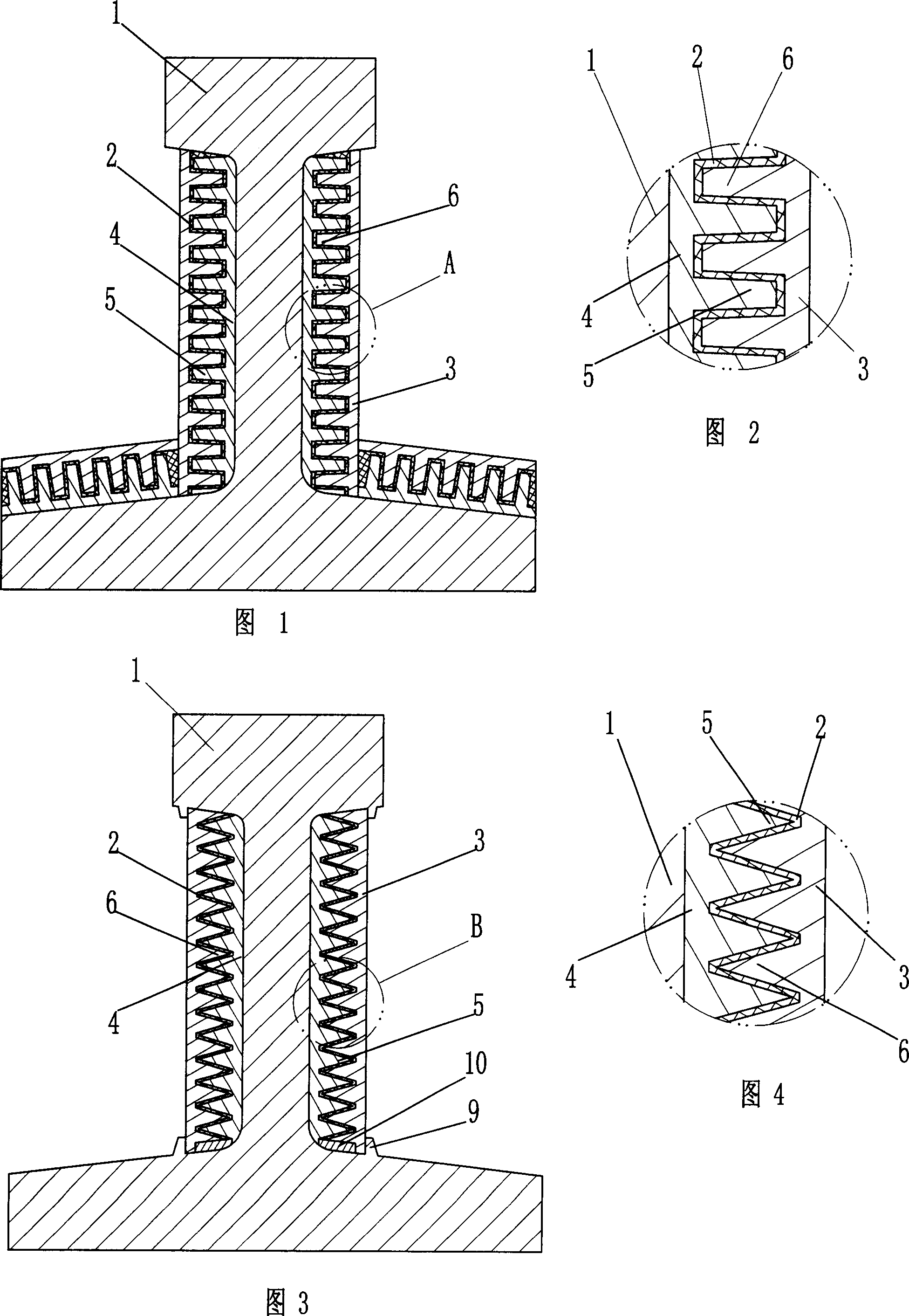
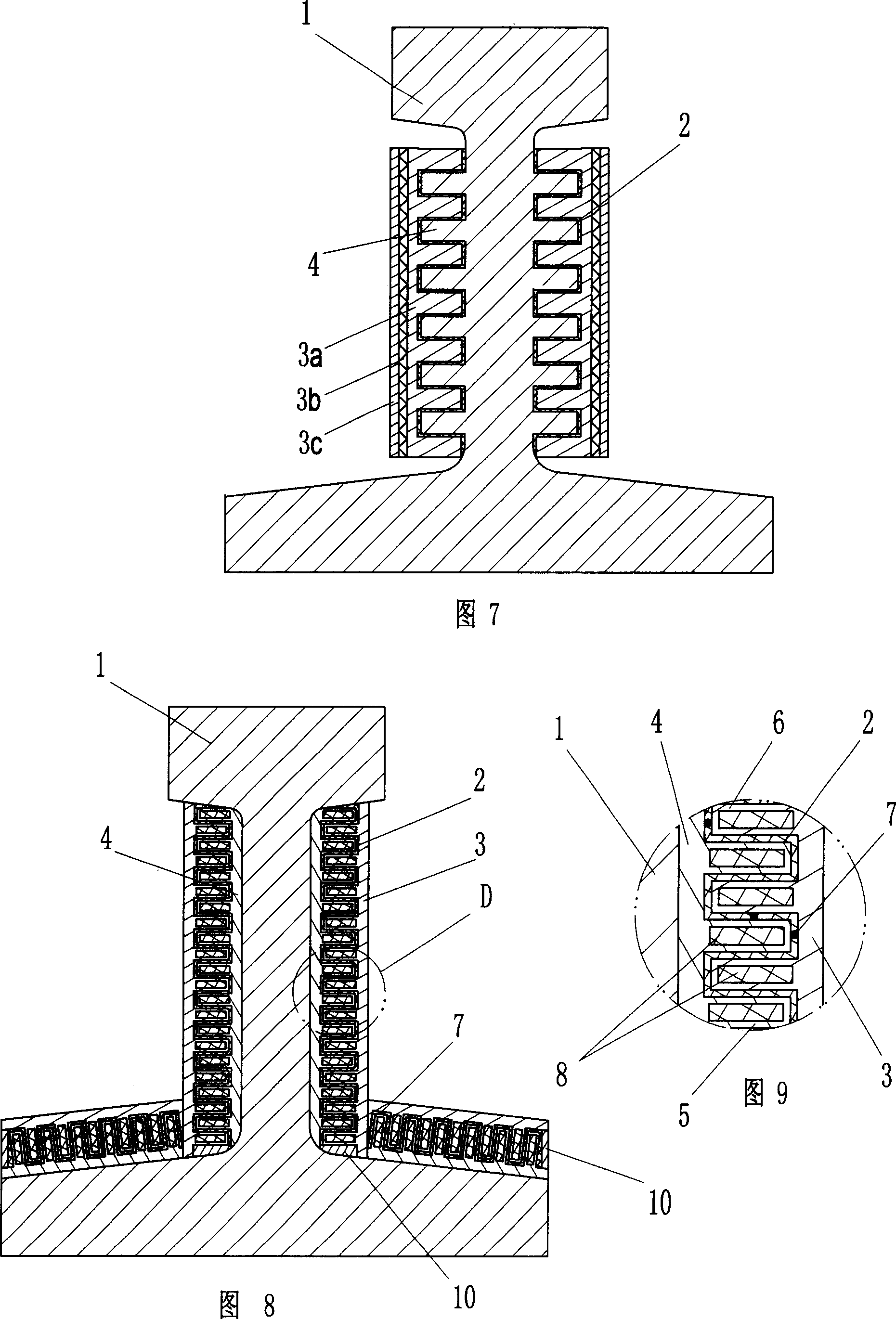
[0031] Such as figure 1 , figure 2 The damping track of the present invention shown includes a track body 1, a damping body 2 made of high-damping rubber and a steel restraint body 3, and a steel connecting body 4 is also arranged between the track body 1 and the damping body 2 to connect The body 4 is multi-point welded to the non-working surfaces on both sides of the track body 1 by resistance welding. For the convenience of construction, the connecting body is divided into two sections for installation on each side of the track body according to its shape change. The connecting body 4 and the damping body 2 have a trapezoidal rib 5 on the side adjacent to the damping body 2, and the trapezoidal rib 6 interlaced with the connecting body trapezoidal rib 5 is arranged on the side adjacent to the damping body 2, and the damping body 2 It is arranged in the matching gap between the connecting body 4 and the constraining body 3, and the connecting body 4 and the constraining bo...
Embodiment 2
[0035] Such as image 3 , Figure 4 The vibration-damping track of the present invention shown includes a track body 1, a damping body 2 made of modified damping asphalt that is liquid at an operating temperature, and an aluminum alloy plate constraining body 3, and an aluminum alloy plate is also arranged between the track body 1 and the damping body 2. The connecting body 4 made of alloy is firmly bonded to the two sides of the rail body 1 by using a high-strength damping material. When bonding with high-strength damping materials, the bonding layer should be as thin as possible to ensure high bonding stiffness. The outer surface of the connecting body 4 has triangular ribs 5 , and the side of the constraining body 3 adjacent to the damping body 2 has triangular ribs 6 interlaced with the ribs 5 . The damping body 2 is arranged in the fitting gap between the connecting body 4 and the constraining body 3 . The restraint structure is locked on the rail by means of the groov...
Embodiment 3
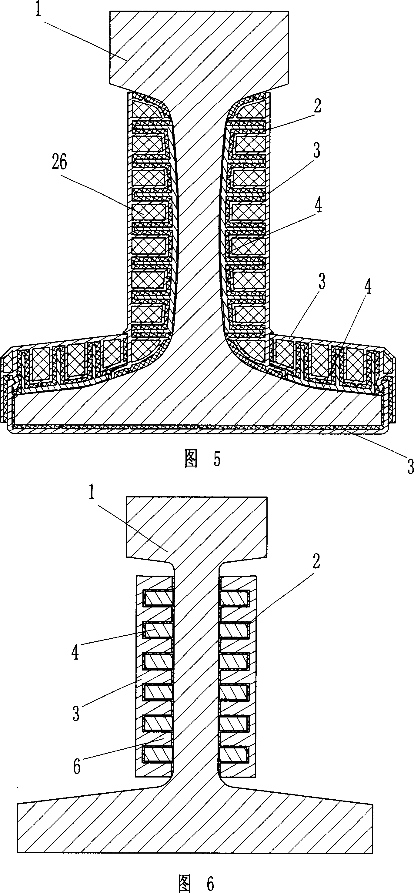
[0039] Such as Figure 5 The vibration-damping track of the present invention shown includes a track body 1, a damping body 2 made of solid modified asphalt, and an aluminum profile constraining body 3, and an aluminum profile connecting body 4 is also arranged between the track body 1 and the damping body 2. The connecting body 4 is firmly bonded to the track body 1 by the elastic adhesive, and the ribs on the connecting body 4 cross-fit with the hollow rectangular bosses on the constraining body 3, and the damping body 2 is arranged between the connecting body and the constraining body within the fitting gap.
[0040] In order to facilitate the construction, the corresponding connecting body and restraining body are made in sections according to the shape of the rail. Since the space at the bottom of the rail is small and the plane area of the rail bottom is large, the connecting body is omitted under the rail, and the connecting body is directly installed between the rest...
PUM
 Abstract
Description
Claims
Application Information
 - R&D
- Intellectual Property
- Life Sciences
- Materials
- Tech Scout
- Unparalleled Data Quality
- Higher Quality Content
- 60% Fewer Hallucinations
Browse by: Latest US Patents, China's latest patents, Technical Efficacy Thesaurus, Application Domain, Technology Topic, Popular Technical Reports.
© 2025 PatSnap. All rights reserved.Legal|Privacy policy|Modern Slavery Act Transparency Statement|Sitemap|About US| Contact US: help@patsnap.com


