
Slide switch apparatus

A sliding switch, switch technology, applied in the direction of electric switches, electrical components, circuits, etc.

Inactive Publication Date: 2012-07-11
PANASONIC CORP
View PDF5 Cites 0 Cited by
  • Summary
  • Abstract
  • Description
  • Claims
  • Application Information

AI Technical Summary

Problems solved by technology

[0007] However, in the structure disclosed in Patent Document 1, since the slide switch 305 is arranged at the lower part of the slide handle 304, there is a possibility that the lens unit 301 (cylinder Body) miniaturization problem
That is, as shown in Figure 17, the lens unit 301 The outer diameter needs at least the thickness dimension R of the sliding handle 304 and the sliding switch 305, which cannot be further miniaturized

Method used

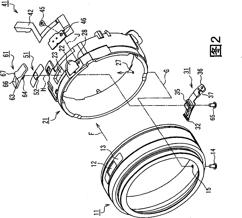
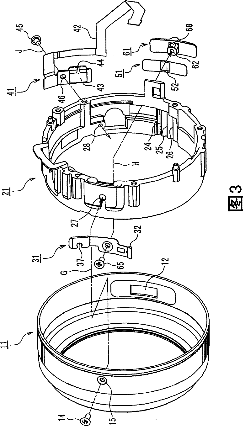

Image

  • Slide switch apparatus
  • Slide switch apparatus
  • Slide switch apparatus

Examples


Embodiment Construction

[0048] (Embodiment 1)

[0049] [1. Overall structure]

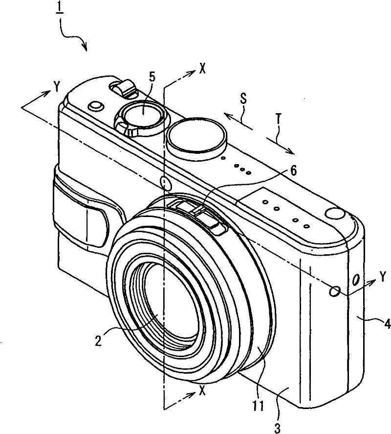
[0050] figure 1 The appearance of the imaging device equipped with the slide switch device of Embodiment 1 is shown. In this embodiment, a digital camera is taken as an example of an imaging device.

[0051] exist figure 1 Among them, the camera body 1 is constituted by, for example, a digital camera, and various circuit boards, imaging elements, and the like are housed in a housing constituted by a front case 3 and a rear case 4 . In addition, various operation parts such as a shutter release button 5 are arranged on the upper surface of the camera body 1 . In addition, in this embodiment, the housing is constituted by the front cabinet 3 and the rear cabinet 4, but it is not limited to this structure.

[0052] The lens unit 2 is disposed on the front housing 3 of the camera body 1 and includes lens groups such as a focus lens and a zoom lens. The lens unit 2 has a substantially cylindrical shape, and a space for...


PUM


Abstract

In a slide switch apparatus of the present invention, a click spring movable along a side surface portion of a housing includes an engagement portion that is engaged with a switch lever and can be switched in accordance with the movement along the side surface portion of the housing, a protrusion that generates a click feeling when moving along the side surface portion of the housing, a positioning rib, and a plate spring portion in which the engagement portion, the protrusion, and the positioning rib are placed and which can be deformed elastically. The positioning rib is placed between the engagement portion and the protrusion in the movement direction of the click spring. Because of this, a slide switch apparatus whose housing can be miniaturized is obtained.

Description

technical field [0001] The present invention relates to a sliding switch device capable of sliding operation in a predetermined direction. In particular, it relates to a slide switch device suitable for mounting in a lens unit of photographic equipment such as a video camera or a digital still camera. Background technique [0002] In recent years, photographic equipment such as video cameras and digital still cameras have developed higher functions and higher performance, and in the function of the lens part, the mode that spans multiple levels has gradually become the mainstream. In addition, the operation of the imaging device is often performed by a switch disposed on the camera body side, but operations related to lens functions may be performed by a switch disposed on the lens barrel portion. As the switches arranged in the lens barrel in this way, for example, as disclosed in Patent Document 1 (Japanese Patent Application Laid-Open No. 3-236006 ), slide switches are m...

Claims


Application Information

Patent Timeline
Patent Type & Authority Patents(China)
IPC IPC(8): H01H15/10
CPCH01H15/02
Inventor 山本修作本部隆弘
Owner PANASONIC CORP
Learn More