Traction device

A pulling device and pulling force technology, applied in the directions of transportation and packaging, coiling strips, thin material processing, etc., can solve the problems of multi-manpower, slowing down the progress of coiling processing, and increasing workload.

Inactive Publication Date: 2007-03-21
NICO STEEL SOLUTION SINGAPORE
View PDF0 Cites 9 Cited by
  • Summary
  • Abstract
  • Description
  • Claims
  • Application Information

AI Technical Summary

Problems solved by technology

[0010] A disadvantage of the above prior art is that the use of this special protective strip or foil increases the workload, thus requiring more manpower and high operating costs
Another di

Method used


Image

  • Traction device
  • Traction device
  • Traction device

Examples


Embodiment Construction

[0030] Reference will now be made to various embodiments according to the invention, examples of which are illustrated in the accompanying drawings and will become apparent to those skilled in the art from the description of the invention. In the different drawings, the same reference numerals designate the same or similar parts.

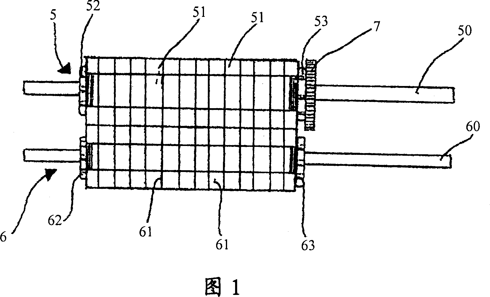
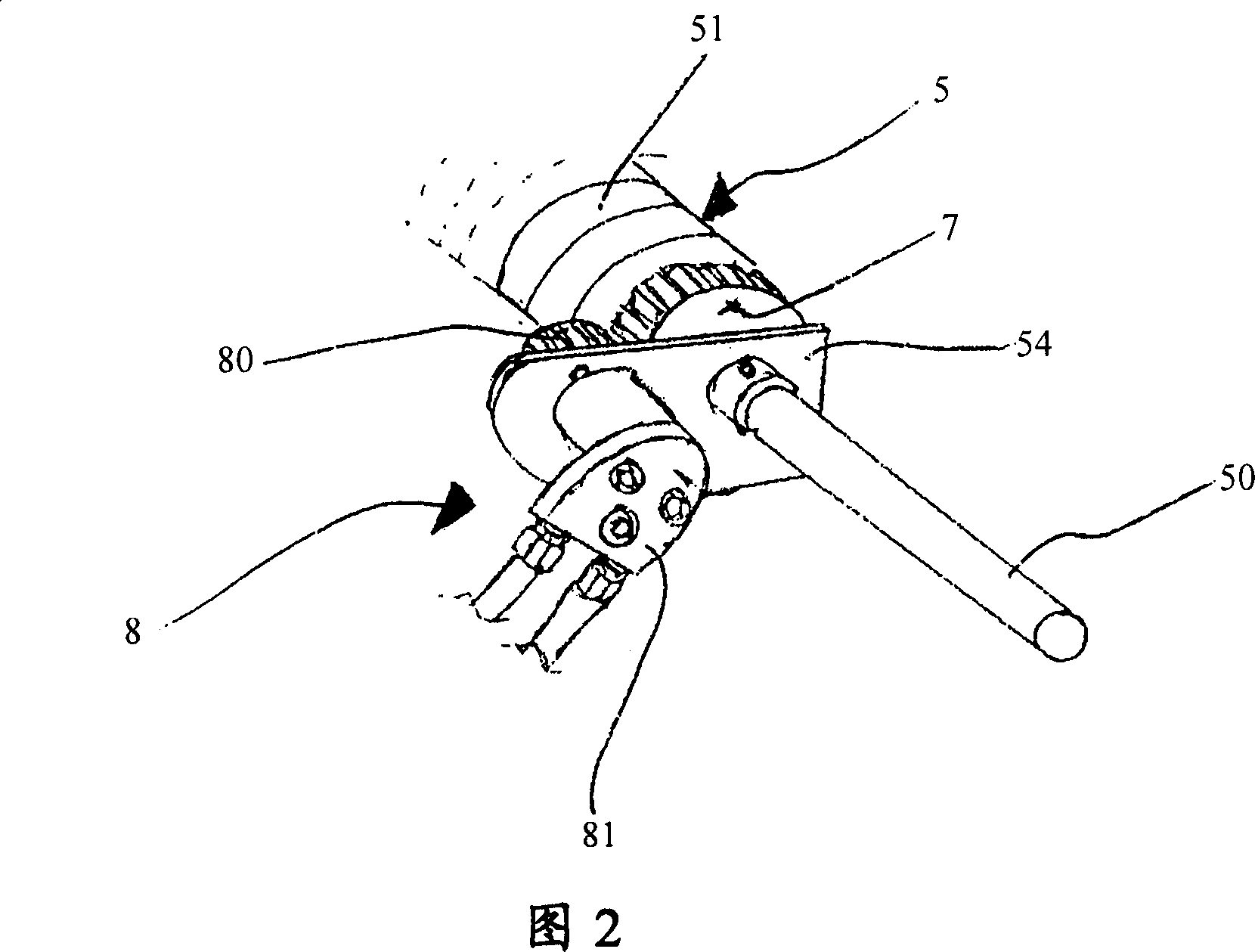
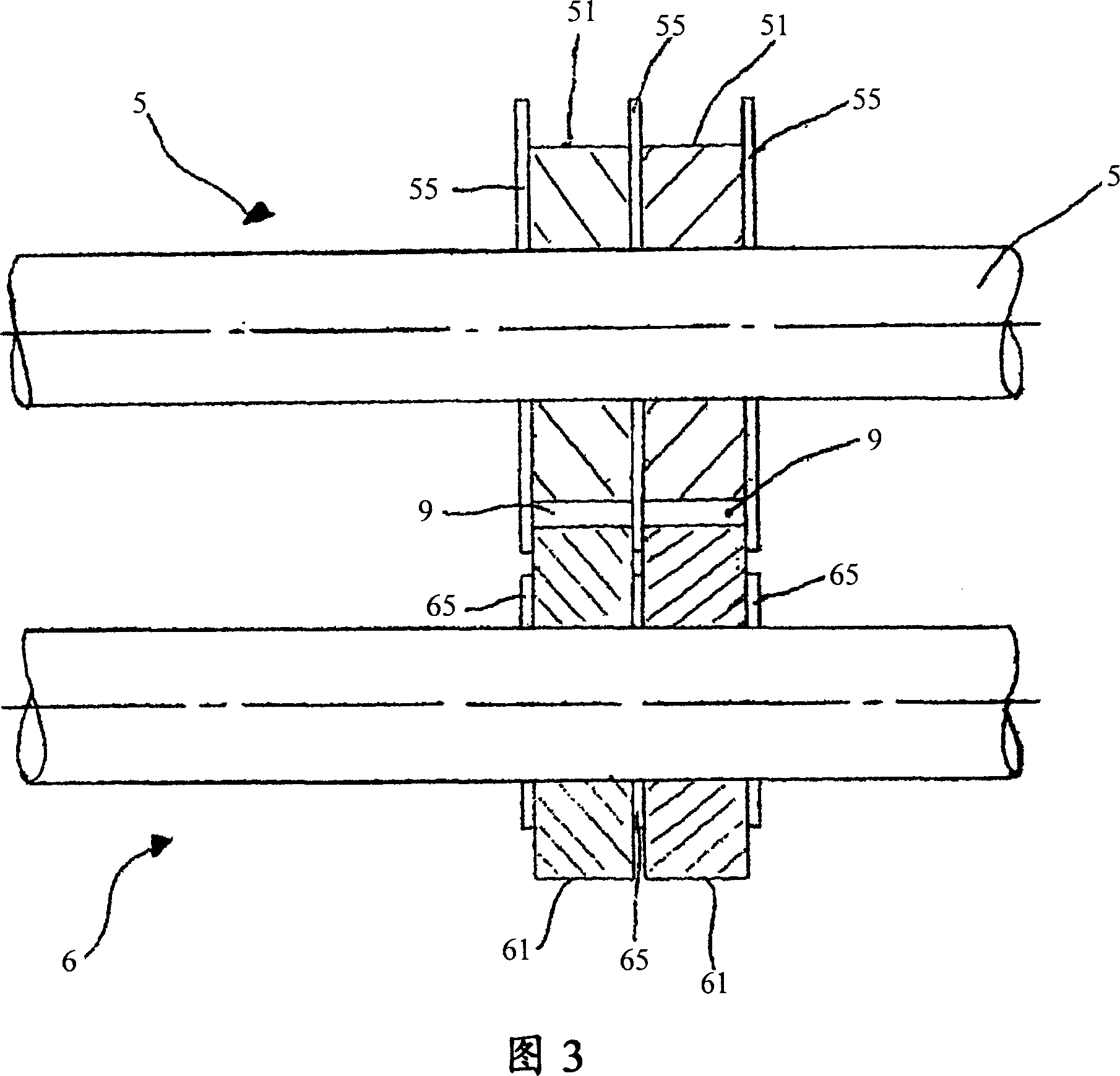
[0031] Figure 1 shows a front view of a pair of rollers according to a preferred embodiment of the present invention. The pair of rolls consists of an upper roll 5 and a lower roll 6 . Both roll 5 and roll 6 are cylindrical rolls and are parallel to each other along the respective axis directions during the coiling process. Each roller 5 and 6 comprises a shaft 50 and 60 respectively; at least one protective ring 51 and 61, in particular made of rubber or polyurethane, is used to protect the coiled strip while guiding it through the two rollers 5 and 6 The surface of the winding strip is protected from damage; spacer rings and contact elements 52 ...


PUM


Abstract

The invention relates to a traction device (1) for straining at least a flat winding strip in a winding process. The traction device (1) comprises at least two rotary rollers (5, 6) connecting with each other through the circumference to guide the flat winding strip to pass through the rollers, wherein at least one roller (5) is connected to a motor driving system (8) for controlling roller speed, thus a predetermined tension is generated on the flat winding strip during the winding process.

Description

technical field [0001] The invention relates to a pulling device for tensioning at least one plated coil strip during a coiling process. Background technique [0002] In general, devices are known for cutting sheet-like flat material into winding strips, which can be coiled or coiled by using a corresponding recoiler. The coiler for winding the respective coiled strips comprises a coiling device to which the individual coiled strips can be fed. Coilers coil individual coiled strips around a single center piece that is removed after coiling, thereby coiling sheet metal for use or sale. These winding strips are generally delivered to the coiler by a feeding device (conveying mechanism). [0003] There are many disadvantages of the above-mentioned mechanical equipment, especially the difficulty of matching the feeding speed of the conveying mechanism with the speed of coiling the strip required by the coiler, thus causing considerable difficulties. Generally speaking, due to...

Claims


Application Information

Patent Timeline
IPC IPC(8): B65H20/02B65H27/00
Inventor 陈志强
Owner NICO STEEL SOLUTION SINGAPORE
Why Eureka
Try Eureka