Glove making machine

A technology of glove machine and unloading rack, which is applied in the field of glove machine, can solve the problems such as difficult to achieve, and achieve the effect of improving quality, less elongation, and less pulling force

Active Publication Date: 2014-08-27
ZHANGJIAGANG PIONEER AUTOMATION MACHINERY EQUIP
View PDF8 Cites 1 Cited by
  • Summary
  • Abstract
  • Description
  • Claims
  • Application Information

AI Technical Summary

Problems solved by technology

The current glove machine is difficult to meet the above requirements

Method used


Image

  • Glove making machine
  • Glove making machine

Examples


Embodiment Construction

[0016] A glove machine according to the present invention will be further described in detail through specific examples below.

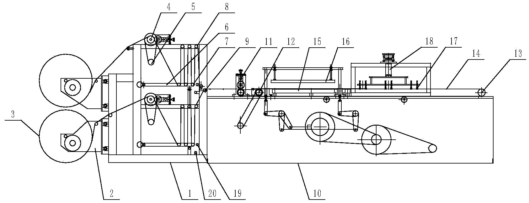
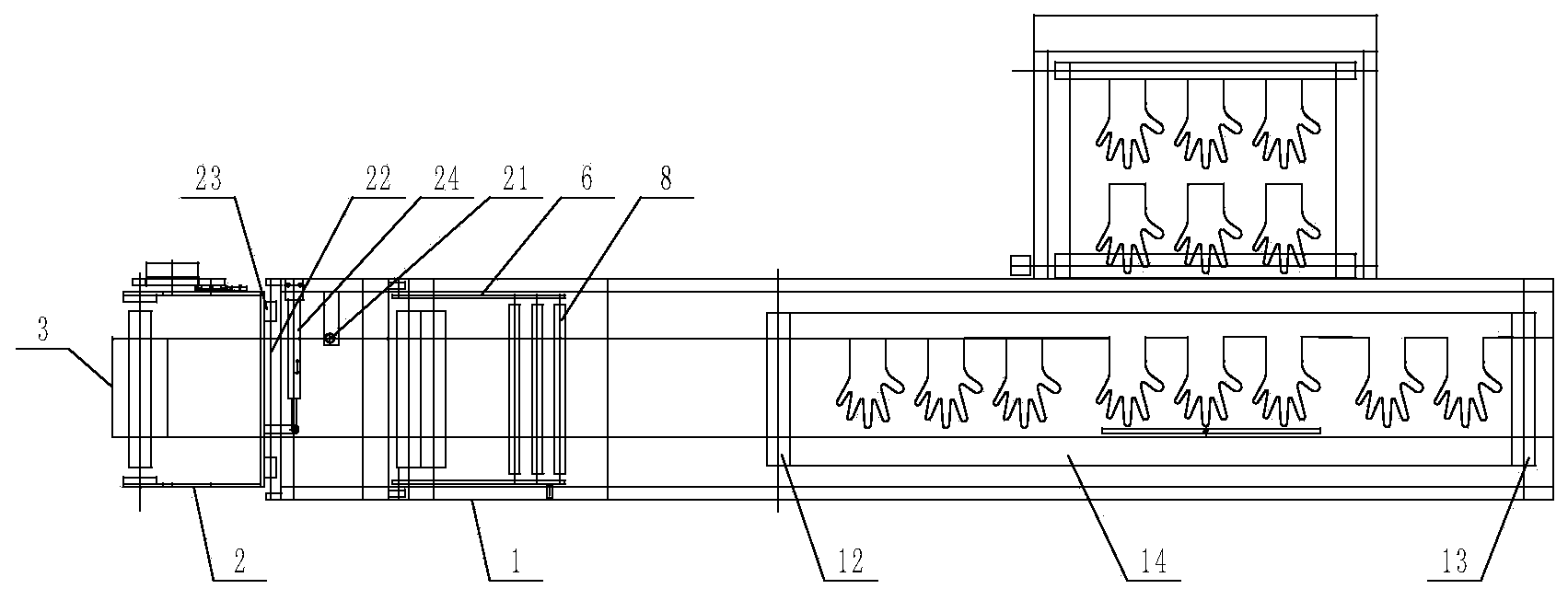
[0017] As shown in Figure l, figure 2 As shown, a glove machine includes a discharging device, a forming mold and a receiving device arranged in sequence. The discharging device includes a discharging rack 1, and the discharging rack 1 is provided with two sets of discharging equipment up and down. The structure of the two sets of unwinding equipment is the same, each set of unwinding equipment includes a roll rack 2 arranged at the front end of the unwinding rack 1, the roll rack 2 is provided with a roll 3, and the unwinding rack 1 is provided with a feeding rubber roller 4 And drive the discharge motor 5 of the discharge rubber roller 4, the discharge rack 1 is also provided with two swing rods 6 on the same plane that are hinged with the discharge rack 1, and several swing rods 6 are arranged between the two swing rods 6. The lower support rod 7...


PUM


Abstract

The invention relates to a glove making machine. The glove making machine comprises an emptying device, a forming mold and a material receiving device which are sequentially arranged, wherein the emptying device comprises an emptying frame, two sets of emptying equipment, namely upper emptying equipment and low emptying equipment are arranged on the emptying frame, each set of emptying equipment comprises a material roll frame arranged at the front end of the emptying frame, and material rolls are arranged in the material roll frames; emptying glue rolls and driving devices are arranged on the emptying frame, and the driving devices are used for driving the emptying glue rolls; two oscillating bars on the same plane are further arranged on the emptying frame, one ends of the oscillating bars are hinged with the emptying frame, a plurality of lower support rods are arranged between the two oscillating bars, and a plurality of upper support rods are arranged at upper positions corresponding to the lower support rods in the emptying frame; transition wheels are arranged at the rear end of the emptying frame; after passing through the emptying glue rolls, plastic films in the material rolls are arranged in an S shape between the lower support rods and the upper support rods in an inserted manner and finally enter the forming mold through the transition wheels. According to the glove making machine, a forming procedure can be carried out continuously; proper tensions of the plastic films can be maintained and the quality of a product is improved.

Description

technical field [0001] The invention relates to a glove machine for producing plastic gloves. Background technique [0002] In the glove machine that produces plastic gloves, the front end uses a discharge device to discharge the material, and then uses a mold to form it, and the rear end performs the material collection. When the mold is forming, the discharge device needs to stop the discharge, and the discharge will continue after the molding is completed. In order to ensure the efficiency of production, the forming process should be carried out as continuously as possible, which requires the discharging device to quickly realize the discharging between the two forming processes, and to ensure that the plastic film maintains an appropriate tension when discharging. The feeding device in the currently used glove machine is difficult to meet the above-mentioned requirements. [0003] In addition, in the discharge device, two sets of discharge equipment are used to dischar...

Claims


Application Information

Patent Timeline
Patent Type & Authority Applications(China)
IPC IPC(8): B29C31/08B29C33/46B29L31/48
Inventor 钱仁明刘晓东吴东
Owner ZHANGJIAGANG PIONEER AUTOMATION MACHINERY EQUIP
Why Eureka
Try Eureka