Belt-retracting device for tightener

A technology of retracting and unwinding belts and tightening, which is used in transportation and packaging, vehicles used for freight, and parts of bundling machinery, etc., which can solve the problems of too small tensioning force of lashing belts, influence of cargo transportation, and insufficient bundling. , to achieve the effect of moderate tension, easy operation, convenient use and safety

Inactive Publication Date: 2009-09-02
ZHEJIANG TOPSUN LOGISTIC CONTROL CO LTD
View PDF1 Cites 2 Cited by
  • Summary
  • Abstract
  • Description
  • Claims
  • Application Information

AI Technical Summary

Problems solved by technology

[0004] However, various fast binding devices in the prior art cannot know the tension of the binding belt during use, which often leads to too small or too large tension of the binding belt; therefore, it is easy to cause damage to the goods due to excessive binding , the binding belt is broken, or the goods transportation is affected because the binding is not tight enough
On the other hand, when binding goods, different goods or the same goods will have different strengths when binding in different positions, which further increases the difficulty of manual control.

Method used


Image

  • Belt-retracting device for tightener
  • Belt-retracting device for tightener
  • Belt-retracting device for tightener

Examples


Embodiment 1

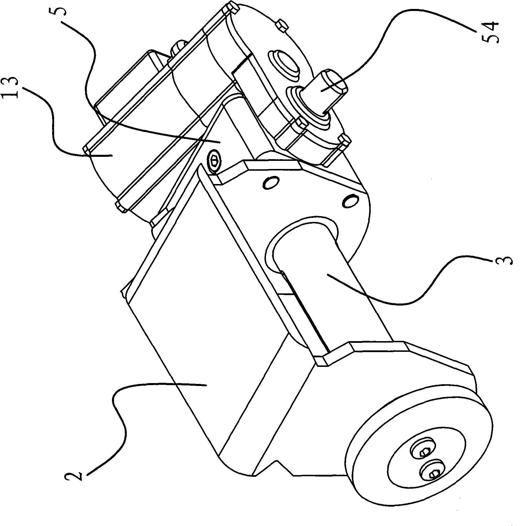
[0034] Such as figure 1 As shown, the tightener has a support 2 on which a belt shaft 3 is connected, and one end of the belt shaft 3 protrudes from the support 2 and is connected with a retractable belt device.

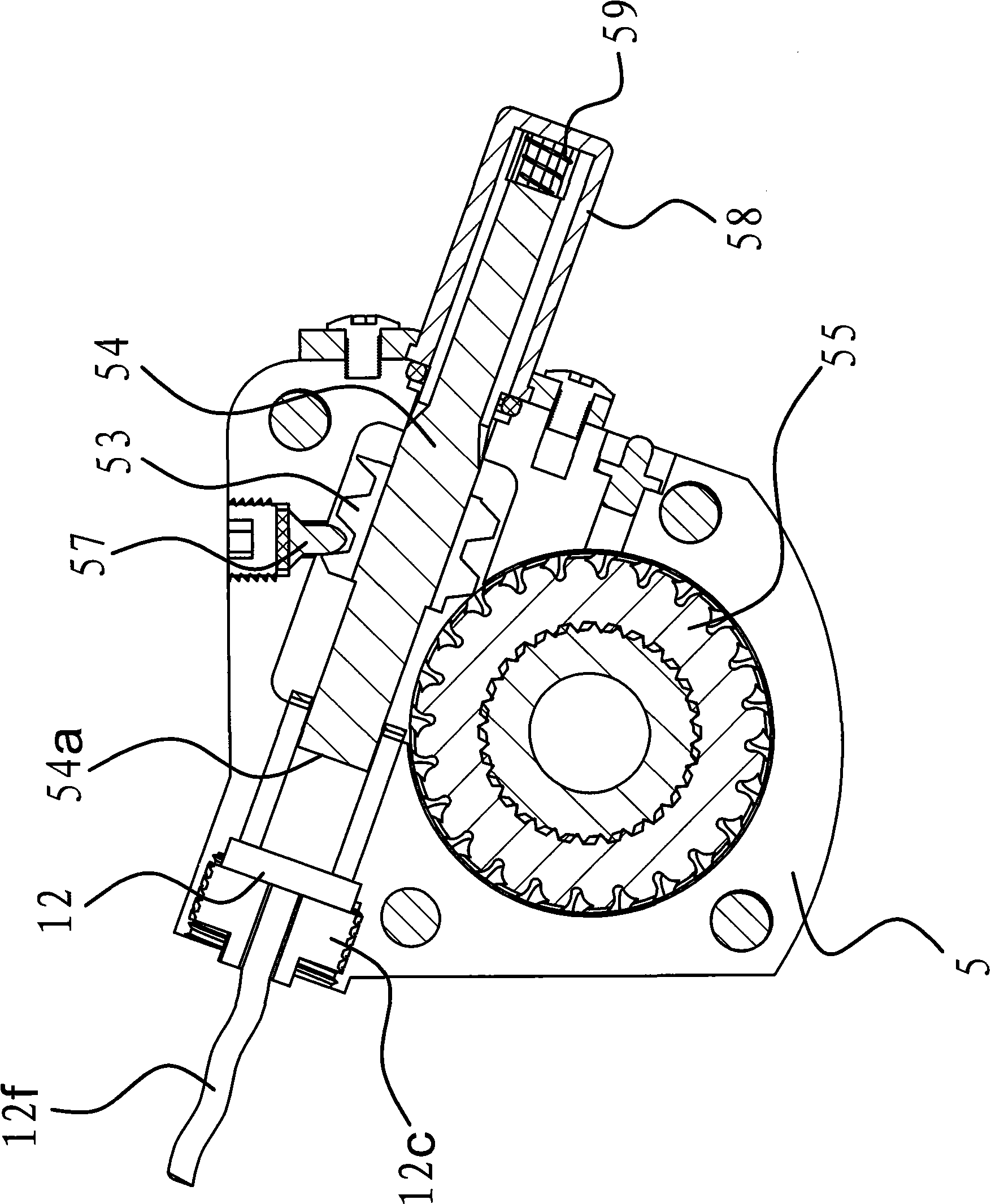
[0035] Such as figure 2 and image 3 Shown, this tightener take-up belt device comprises parts such as casing 5, worm screw 53, worm shaft 54, worm wheel 55, sensor 12, locator 57, rotating sleeve 58, spring 59.

[0036]A box body 5 with a cavity inside is fixedly attached to the side of the bracket 2 , and a worm 53 , a worm shaft 54 ​​and a worm wheel 55 are arranged in the box body 5 . The worm 53 is sleeved on the worm shaft 54 ​​and the two are fixedly connected together. Of course, the worm 53 and the worm shaft 54 ​​here can also adopt an integrated structure. The worm wheel 55 is fixedly connected to the protruding end of the belt shaft 3 , and the worm shaft 54 ​​is arranged on the side of the worm wheel 55 and can move in the casing 5 along its axial di...

Embodiment 2

[0043] In this example, if Figure 4 and 5 As shown, a guiding mechanism capable of driving the worm shaft 54 ​​to move along its axial direction is provided between the box body 5 and the worm 53 when the worm shaft 54 ​​rotates. The guiding mechanism is a threaded connection section 61 provided on the worm shaft 54 ​​and a threaded connection hole 62 provided on the box body 5, and the threaded connection section 61 and the threaded connection hole 62 can be threadedly connected, when the worm shaft 54 ​​moves along its axial direction The rear worm 53 is engaged with the worm wheel 55 and the threaded connection section 61 is disengaged from the threaded connection hole 62 . The rest are similar to those in Example 1, and will not be described in detail.

[0044] When the threaded connection section 61 is connected with the threaded connection hole 62 , it can be moved along the thread during the process of turning the worm shaft 54 ​​. Once the threaded section 61 of th...


PUM


Abstract

The invention provides a belt-retracting device for a tightener, and relates to a tightener. The device solves the problems that the prior belt-retracting device for the tightener cannot detect the tension of a binding belt and has instability, troublesome operation, complicated structure, and the like. In the belt-retracting device, a bracket of the tightener is provided with a rotatable belt shaft of which one end extends out of the bracket. The device comprises a case body, a worm, a worm shaft and a worm wheel, wherein the worm is sleeved on and fixedly connected with the worm shaft. The device also comprises a sensor. When the worm shaft moves, the inner end face of the worm shaft can be supported against the sensor, and make the sensor generate signals which correspond to the tension of the binding belt. The sensor comprises a flaky compressed block. One end face of the compressed block faces towards the inner end face of the worm shaft, while the other end face faces towards the case body and is provided with a plurality of evenly-distributed resistance strain gages. The belt-retracting device has the advantages of simple structure, convenient operation, intelligence, safe use, and the like.

Description

technical field [0001] The invention belongs to the technical field of machinery, and relates to a winch and a winch for bundling goods in the process of logistics transportation, in particular to a belt retracting device for a belt shaft in the winch. Background technique [0002] During the transportation of goods, the goods usually need to be bundled to prevent the goods from falling off or colliding with each other during transportation and causing loss or damage. Although the method of directly binding with ropes is very common, it is time-consuming and laborious, and it is difficult to tie the goods tightly. The tightener is an advanced binding tool. It is convenient and safe to use the tightener to bind the goods, and is welcomed by the majority of transport personnel. Existing tighteners are usually made up of support, band shaft and binding band. The tape shaft is connected to the bracket and the tape shaft is rotatable, and the binding tape is wound on the tape ...

Claims


Application Information

Patent Timeline
Patent Type & Authority Applications(China)
IPC IPC(8): B65B13/22B65B13/18B60P7/06
Inventor 阮卜琴
Owner ZHEJIANG TOPSUN LOGISTIC CONTROL CO LTD
Why Eureka
Try Eureka