Horizontal flux flat-plate type permanent-magnetic linear electric machine

A permanent magnet linear motor, transverse magnetic flux technology, applied in electrical components, electromechanical devices, electric components, etc., can solve problems such as low force density, large edge effect, and difficulty in producing laminations

Inactive Publication Date: 2007-03-21
哈工大(张家港)智能装备及新材料技术产业化研究院有限公司
View PDF0 Cites 36 Cited by
  • Summary
  • Abstract
  • Description
  • Claims
  • Application Information

AI Technical Summary

Problems solved by technology

[0003] In order to solve the problem that the traditional flat-plate permanent magnet linear motors are axial flux type, there is a large edge effect, a

Method used


Image

  • Horizontal flux flat-plate type permanent-magnetic linear electric machine
  • Horizontal flux flat-plate type permanent-magnetic linear electric machine
  • Horizontal flux flat-plate type permanent-magnetic linear electric machine

Examples


specific Embodiment approach 1

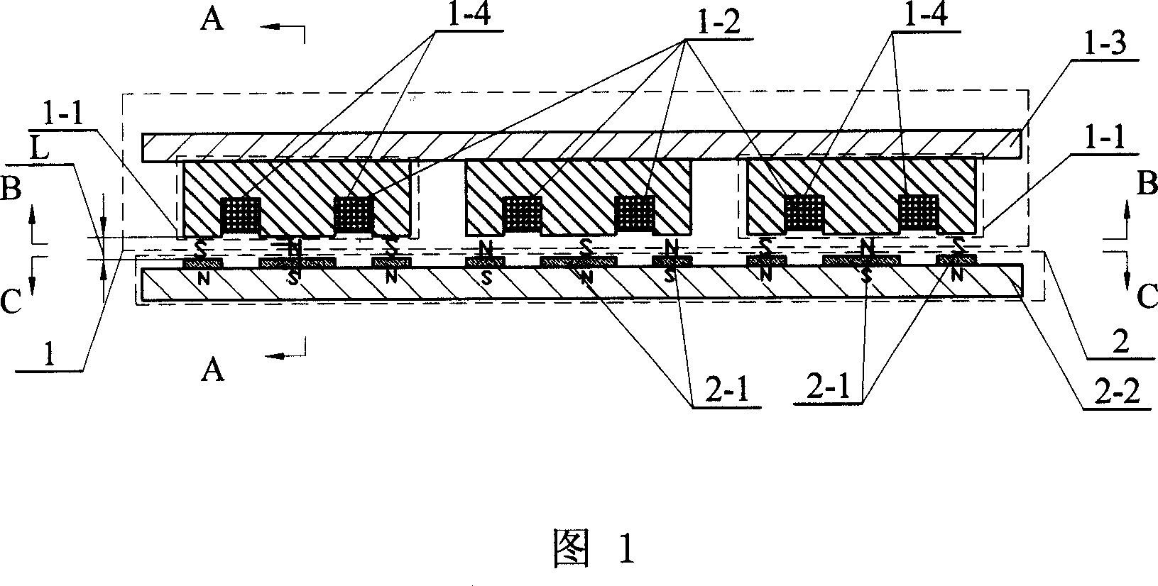
[0011] Specific implementation mode 1: This implementation mode is described in conjunction with FIG. 1 , FIG. 2 , FIG. 3 , and FIG. 4 ;

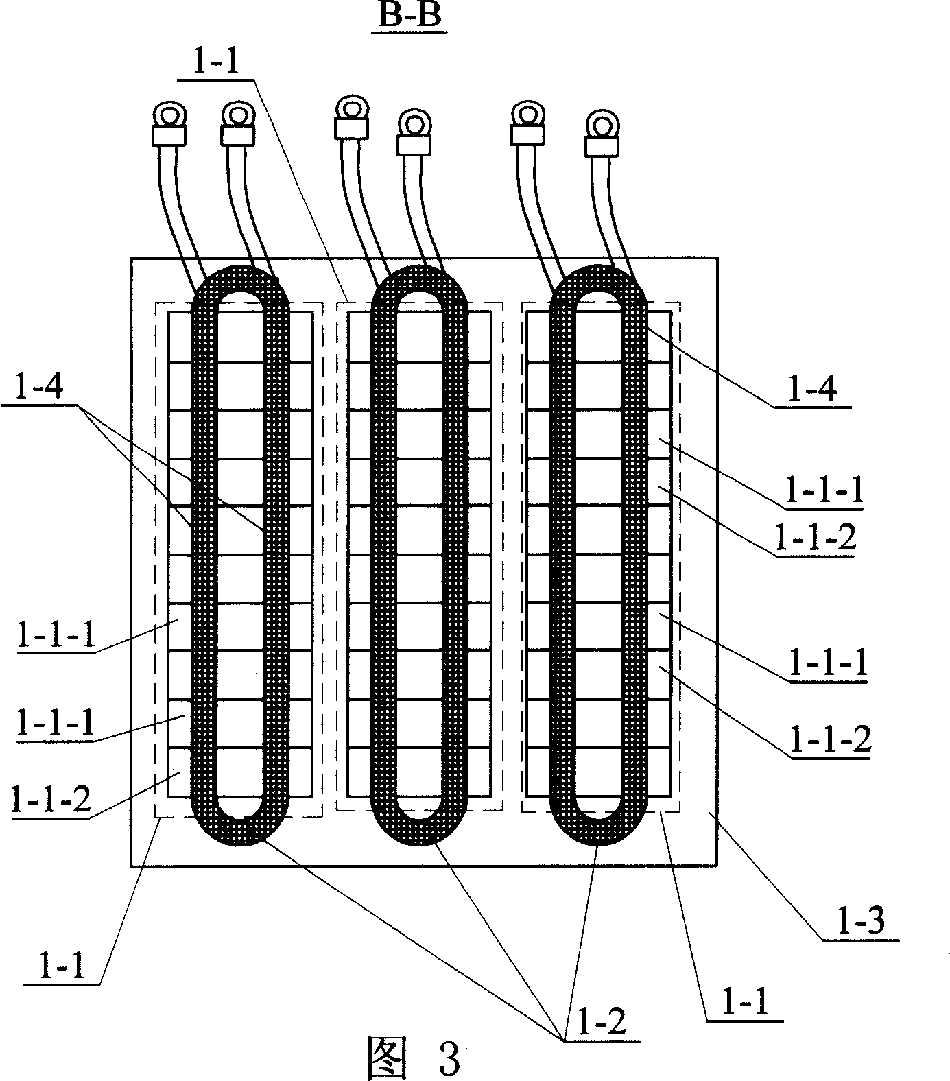
[0012] This embodiment is composed of a first primary 1 and a permanent magnet secondary 2; the first primary 1 is composed of a plurality of E-shaped cores 1-1, windings 1-2, and a bottom plate 1-3;

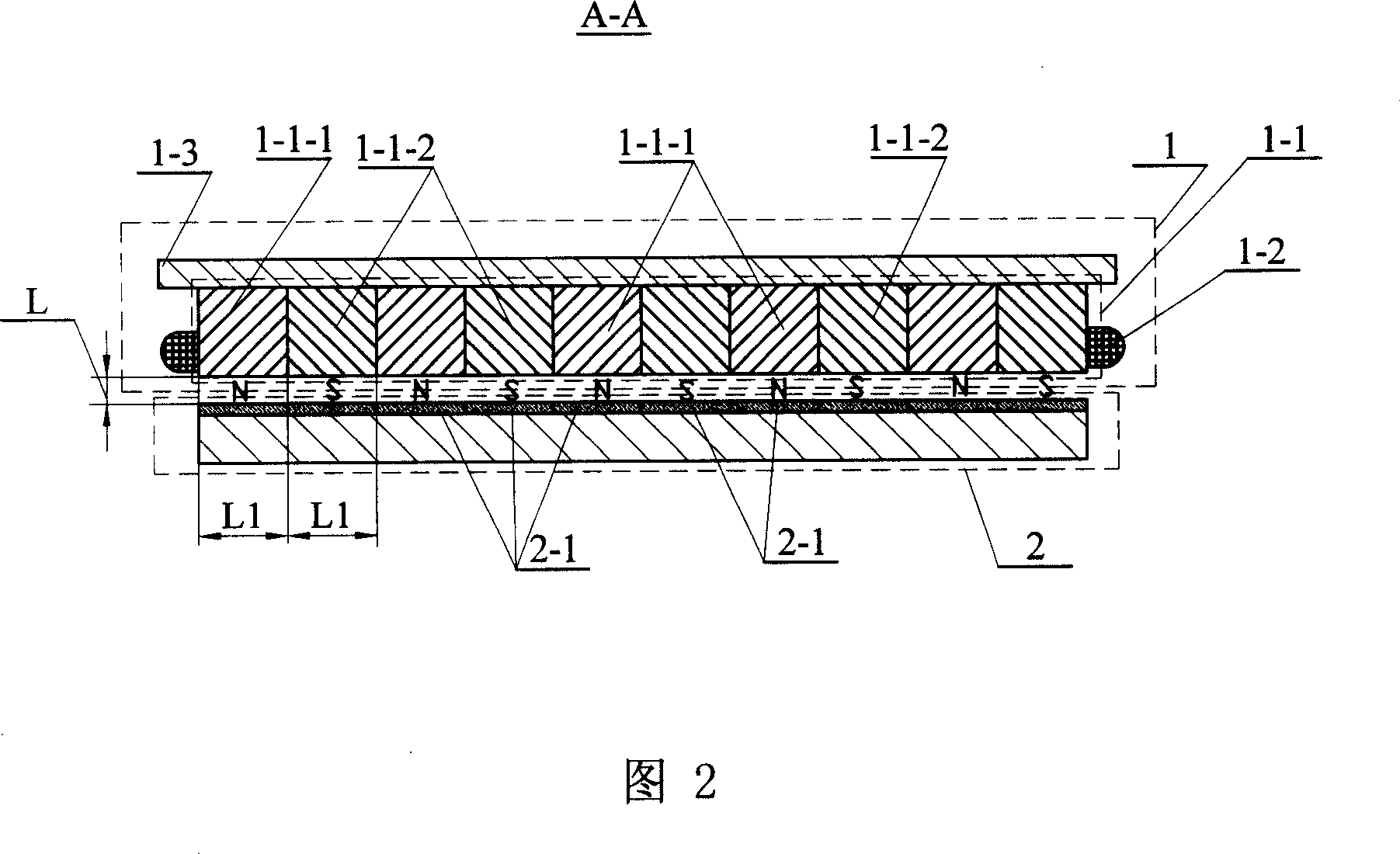
[0013] The E-shaped outer bottom end surfaces of multiple E-shaped cores 1-1 are arranged side by side with gaps on one side of the bottom plate 1-3; the slots 1-4 of multiple E-shaped cores 1-1 are jointly embedded with windings 1- 2; each E-shaped core 1-1 is composed of a plurality of E-shaped magnetic permeable blocks 1-1-1 and a plurality of E-shaped magnetic isolation blocks 1-1-2 arranged evenly with each other; all of the first primary 1 There is a gap L between the end faces of the three claws of the E-shaped core 1-1 and one end face of the permanent magnet secondary 2;

[0014] In one end face of the permanent magnet secondary 2, ...

specific Embodiment approach 2

[0016] Embodiment 2: This embodiment is described with reference to FIG. 7 . On the basis of Embodiment 1, each E-shaped magnetic permeable block 1-1-1 is composed of several iron core sheets 1-1-3 superimposed.

specific Embodiment approach 3

[0017] Specific embodiment three: This embodiment is described in conjunction with Fig. 5 and Fig. 6. On the basis of specific embodiment one, a second primary 3 is added, and the composition and connection relationship of the second primary 3 are the same as those of the first primary 1. The other side end face of the magnetic secondary 2 is increased with three claw surfaces of each E-type magnetic permeable block 3-1-1 in the second primary 3 or three claw faces of each E-type magnetic isolation block 3-1-2. The permanent magnet blocks 2-3 with claw faces facing each other respectively, the arrangement mode and magnetization direction of all permanent magnet blocks 2-3 are the same as the arrangement mode and magnetization direction of all permanent magnet blocks 2-1; The winding 1-2 is connected in series with the winding 2-2 in the second primary 3 in the same phase and forward direction. This embodiment can improve the force density of the motor and eliminate the adverse...


PUM


Abstract

This invention relates to a lateral flux flat permanent magnet linear motor, in which, E-type outer bottom surfaces of multiple E-type cores are arrayed on a side panel of a bottom board side by side in gaps, windings are inlaid in the grooves of the multiple E-type cores, end surfaces of three claws of all E-cores of the first primary have gaps with end surface of one side of a secondary, and magnet blocks are set on a side end face of the secondary and opposite to the three claw surfaces of each E-type magnet-conduction block in the first primary or three claw surfaces of each magnet-isolating block separately. The moving direction of runners in this invention is vertical to the plane the master magnetic flux places at and the manufacture of iron core punch plates is simple compared with traditional magnet linear motors.

Description

technical field [0001] The invention relates to the technical field of permanent magnet linear motors. Background technique [0002] The traditional flat-plate permanent magnet linear motors are all axial flux type, with large edge effects. If the stator is long, it is difficult to produce laminations, and the force density is low. Contents of the invention [0003] In order to solve the problem that the traditional flat-plate permanent magnet linear motors are axial flux type, there is a large edge effect, and if the stator is long, it is difficult to produce laminations and the force density is small. A transverse flux flat-plate permanent magnet linear motor is proposed. [0004] The present invention includes a first primary 1 and a permanent magnet secondary 2; the first primary 1 is composed of a plurality of E-shaped cores 1-1, windings 1-2, and a bottom plate 1-3; [0005] The E-shaped outer bottom end surfaces of multiple E-shaped cores 1-1 are arranged side by ...

Claims


Application Information

Patent Timeline
IPC IPC(8): H02K41/02H02K41/03
Inventor 郑萍薛斌峰李斐斐沈琳
Owner 哈工大(张家港)智能装备及新材料技术产业化研究院有限公司
Why Eureka
Try Eureka